
Choosing High-Precision GNSS Receivers, Boards, and Antennas
Hardware programs rarely fail a GNSS specification by a centimetre. They fail on integration debt: an interface that cannot be re-sourced, an antenna that cannot be relocated, or a module whose documentation stops at the evaluation board. The choice between a complete RTK receiver, an RTK board, an RTK GNSS module and a smart antenna is an architecture decision that has to stay serviceable from first prototype through volume production and field service.
This technical guide is written for hardware and systems engineers building UAVs, precision agriculture equipment, autonomous vehicles, robotics and surveying instruments. It uses Jumpstar's High Precision GNSS Solutions portfolio as the worked example, and it keeps three things separate: what the documentation states, what the integrator still owns, and what must be verified before design freeze. All accuracy, interface and capacity figures below are manufacturer- or supplier-stated and are not independent laboratory results.
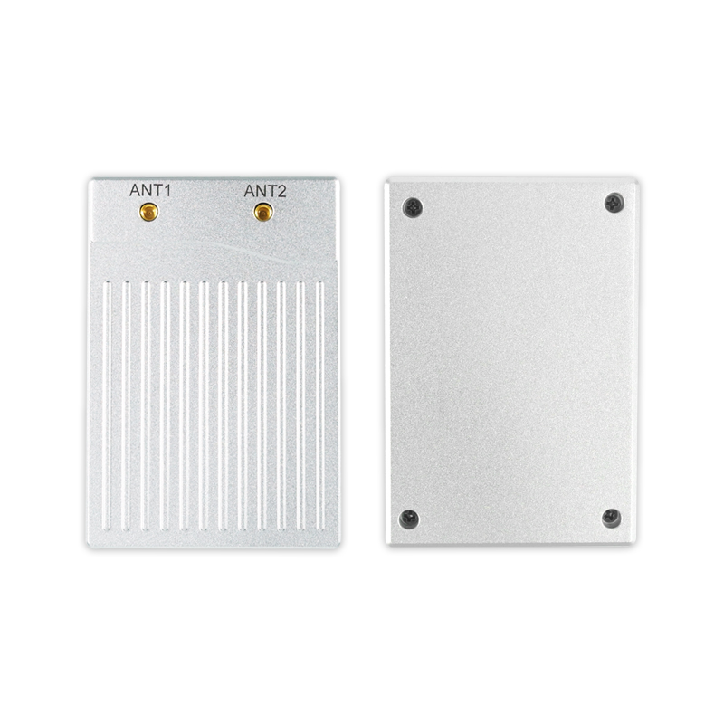
The decision behind receiver vs board vs module
The form-factor question is not about which option is more accurate. The same RTK engine family can appear at several integration levels, so the meaningful question is where you want to own RF design, enclosure, EMC, certification and field service.
Four decisions are coupled, and they are often made in the wrong order:
- Accuracy class and error statistic. RTK versus single-point, and CEP versus RMS. A module quoted at 1.0 cm + 1 ppm CEP and a terminal quoted at 2 cm ± 1 ppm RMS are not the same claim.
- Integration boundary. Turnkey unit, board-level assembly, module, or smart antenna.
- Antenna and RF architecture. Separate antenna, integrated smart antenna, or dual-antenna heading.
- Lifecycle path. Change notification, revision history, test evidence, capacity and support after the design is frozen.
The first three get attention in the schematic review. The fourth gets attention three years later, when a firmware revision, a discontinued connector or an expiring certificate lands in the middle of a production run. A practical test for any candidate: name the party that will answer a field failure in year three. If the answer is unclear, the interface is not fully specified.
What the 2026 supply landscape means for a multi-year design
Demand context matters less than documentation quality, but it explains why the supply base looks crowded. Data Insights Reports estimated the high-precision GNSS receiver market at USD 3.10 billion in 2025, while Fortune Business Insights valued the wider GNSS market at USD 335.04 billion in 2025 with a projection of USD 844.55 billion by 2034. Both are commercial research estimates rather than audited shipment data, so they indicate direction, not a planning figure for a single product line.
The practical consequence for engineers is uneven documentation. Accuracy claims are published in different statistics, under different conditions, with different correction sources — sometimes within one supplier's own catalogue. A 50% CEP figure in open sky, an RMS figure from a vehicle roof and a vendor field report cannot be ranked against each other without a common test setup. That is why this guide screens capability and integration fit rather than ranking accuracy.
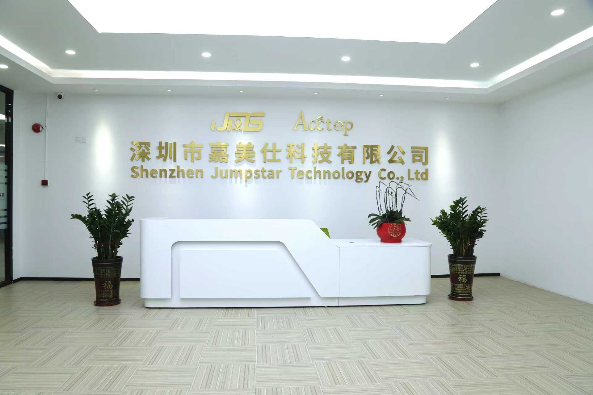
Jumpstar is a Shenzhen-based manufacturer of high-precision GNSS and IoT location solutions, established in 2013, with 200 employees, a 5,000 m² facility and a 20-engineer R&D team. The portfolio documentation states a monthly production capacity of 50,000 units, a typical lead time of 30 days, and export markets in the EU, Middle East and USA. Quality management is covered by ISO 9001:2015 certificate UQ231801R2, effective 11 December 2023 and valid until 10 December 2026 — a date that matters for any programme running past the current design cycle.
The building blocks, one by one
Complete RTK receivers: lowest integration effort
A complete RTK receiver is an integrated unit in which the GNSS engine, RF path and often the antenna and communications sit inside one enclosure. Jumpstar's comparison documentation describes the P-Box-X10 as a turnkey integrated receiver with plug-and-play maintenance and remote OTA updates, and states that no RF engineer is required on the integrator side; its listed uses are port logistics, precision agriculture and heavy-duty vehicle retrofitting.
What that buys: your team owns mounting, harness, host software and site survey instead of RF layout and antenna tuning. What it costs: the enclosure, connector set and environmental rating become the vendor's decisions, and per-unit cost does not fall as fast as it does with a module. For a long programme, ask for the OTA policy, the service procedure, the connector specification and the environmental rating in writing — the last two are not stated in the product materials reviewed here.
RTK boards: the vendor holds the RF design
A board-level assembly packages the RTK module with carrier electronics, power conditioning, connectors and sometimes shielding. The responsibility split is the reason to choose it: the vendor owns the RF and the engine, while you own the enclosure, EMC behaviour, harness and thermal path. Jumpstar product materials describe RTK positioning boards with centimetre-level positioning, dual-frequency RTK and dual-antenna heading. For a specific board, request the board-level mechanical drawing, the interface list, the firmware update path and the datasheet of the module underneath it, because a board revision can change all three.
RTK GNSS modules: full control, full responsibility
An RTK GNSS module is the engine alone. You supply the antenna, RF layout, power conditioning, enclosure and thermal design. The portfolio shows how widely the electrical envelope varies between modules, which is why the module shortlist has to follow the power architecture rather than the other way round:
- JS-ARK28-3 — 200 tracking channels, dual-band multi-constellation reception covering GPS L1/L5, BDS, Galileo, GLONASS, QZSS, IRNSS and SBAS, with RTK accuracy of 1.0 cm + 1 ppm horizontal and 1.5 cm + 1 ppm vertical at 50% CEP in open sky.
- JS-ANK45-2 — 45.0 × 45.0 × 12.7 mm ± 0.3 mm, under 40 g, 3.0–5.5 V (typical 5.0 V), 1408 channels, cold start under 30 s, RTK initialisation under 5 s, RTK horizontal 1.5 cm + 1 ppm and vertical 2.0 cm + 1 ppm RMS, NMEA 0183, Unicore and RTCM3.X, operating from −40 °C to +85 °C and RoHS compliant. Listed applications include UAVs, precision agriculture, automotive, smart ports, logistics and surveying.
- JS-ARK37-3 — 36.00 × 36.00 × 9.70 mm ± 0.2 mm, under 21 g, rated 3.5–12.0 V (typical 5 V), which suits designs that cannot afford a narrow supply window.
- JS-RK26-U — a compact GNSS+INS module at 16.2 × 12.2 × 2.3 mm and under 1.1 g, 200 tracking channels, cold start 28 s, RTK horizontal 1.0 cm + 1 ppm, speed accuracy 0.1 m/s CEP, 20 Hz maximum update rate, NMEA 0183 and RTCM3.X, −40 °C to +85 °C, designed for automotive navigation and rail transit intelligent positioning.
- JS-A56U9D — a multi-band receiver with 192 search and 60 tracking channels, time pulse accuracy of RMS 30 ns (99% 60 ns), dynamic heading accuracy of 0.3°, velocity limit 500 m/s and altitude limit 80,000 m, supporting NMEA 0183 V4.11/V4.0/V4.1, RTCM 3.3 and UBX.
GNSS modules without RTK: sometimes the correct answer
A single-point GNSS module is not a downgraded RTK module; it is a different cost and architecture point. Jumpstar's JS-AP26-H is designed for car navigation and vehicle tracking, with tracking and navigation sensitivity of −162 dBm. The JS-SK40 lists tracking sensitivity of −150 dBm (20 dB-Hz) and acquisition sensitivity of −140 dBm (30 dB-Hz). The JS-AP10-H covers GPS L1C/A, BDS B1I/B1C, Galileo E1B/C, SBAS L1C/A and QZSS L1C/A. Where the platform needs continuity rather than centimetres, the JS-TP26-U combines GNSS with an IMU for intelligent driving and vehicle control, quoting single-point horizontal accuracy of 1.0 m CEP on L1+L5, 2.5 m CEP on L1, GNSS+INS under 1.5 m CEP and a 10 Hz maximum update rate.
The selection rule is blunt: if the requirement is lane-level or centimetre-level positioning, a single-point module cannot substitute for RTK, and the integration effort saved will be repaid in the field.
Smart antennas and antenna choice
Antenna decisions are often made last and cost the most to reverse. A separate GNSS antenna gives control over placement, gain and multi-antenna geometry; a smart antenna integrates the antenna, receiver and communications into one housing.
The X28 datasheet reports rover and base-station dual-mode operation, RTK accuracy of 2.5 cm ± 1 ppm, and support for GPRS, Bluetooth/Wi-Fi, LoRa and CAN. That combination shortens RF work in base-and-rover deployments and removes cable-loss uncertainty between antenna and receiver. The trade-off is placement freedom: when heading comes from a second antenna rather than a magnetometer or gyro, baseline length and mounting repeatability become mechanical tolerances rather than firmware settings. The JS-A56U9D's 0.3° dynamic heading accuracy is only meaningful if the antenna baseline holds its geometry under vibration.
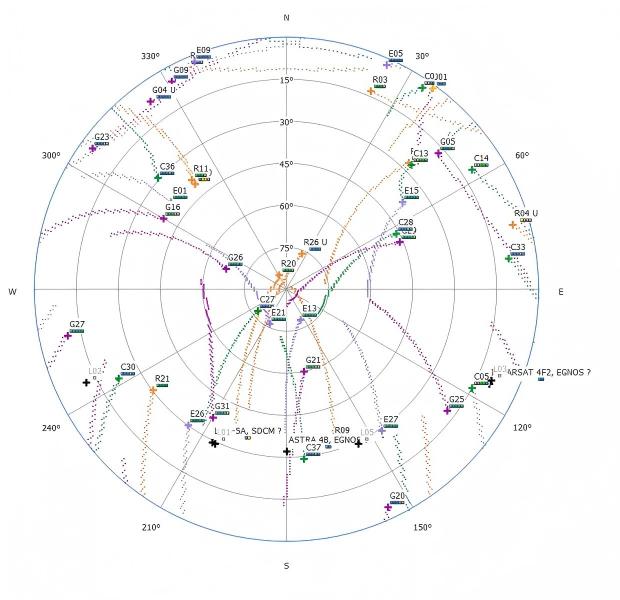
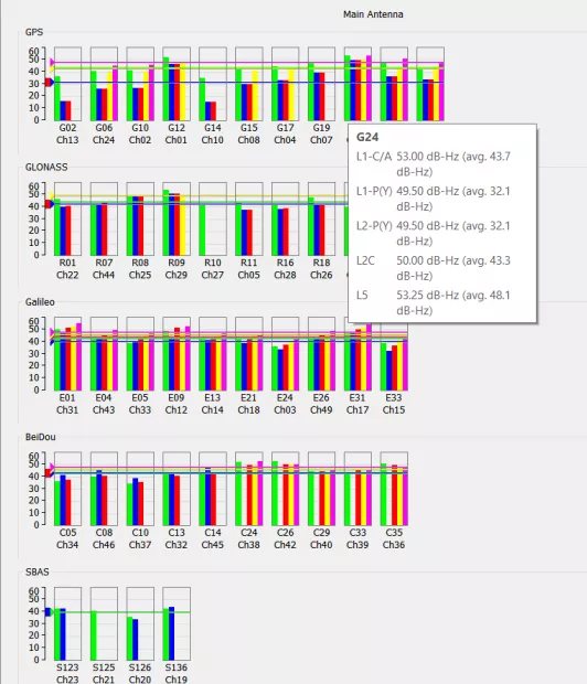
Two measurements belong in every antenna evaluation. Carrier-to-noise ratio per satellite tells you whether the installation is starving the receiver before you blame the engine. Multipath behaviour tells you whether the site will hold a fixed solution. On the engine side, Jumpstar's module risk-control documentation describes AIM+ full-spectrum interference suppression, triple-channel adaptive narrowband notch filtering and APME multipath mitigation, together with Galileo OSNMA navigation-message authentication and RAIM integrity monitoring to reject forged signals.
Comparison: what each option asks you to own
| Option | What the integrator receives | Documented interface / capability | What you still own | Lifecycle question |
|---|---|---|---|---|
| Complete RTK receiver (P-Box-X10) | Turnkey integrated unit | Plug-and-play maintenance with remote OTA; no RF engineer required (company comparison material) | Mounting, harness, host software, site survey | OTA policy, service procedure, environmental rating |
| RTK board | Board-level assembly around an RTK engine | Centimetre-level positioning, dual-frequency RTK, dual-antenna heading (company product materials) | Enclosure, EMC, connectors, thermal path | Board revision history and the module datasheet underneath |
| RTK GNSS module (JS-ARK28-3, JS-ANK45-2) | Module with RF front end | 200 channels, GPS L1/L5, BDS, Galileo, GLONASS, QZSS, IRNSS, SBAS; 1.0 cm + 1 ppm H / 1.5 cm + 1 ppm V at 50% CEP; ANK45-2 adds 1408 channels, NMEA 0183/Unicore/RTCM3.X, −40 to +85 °C | Antenna, RF layout, power, enclosure | Change notification and long-term availability |
| Compact GNSS+INS module (JS-RK26-U) | 16.2 × 12.2 × 2.3 mm, under 1.1 g | 200 channels, cold start 28 s, RTK 1.0 cm + 1 ppm, 20 Hz, NMEA 0183, RTCM3.X | Vehicle model, INS calibration, firmware integration | Firmware update path and calibration support |
| Heading module (JS-A56U9D) | Dual-antenna heading capability | 0.3° dynamic heading, 192 search / 60 tracking channels, time pulse RMS 30 ns, NMEA 0183, RTCM 3.3, UBX | Baseline geometry, antenna mounting, vibration tolerance | Baseline tolerance and mounting repeatability |
| Smart antenna (X28) | Antenna, receiver and communications in one housing | Rover/base dual mode, 2.5 cm ± 1 ppm RTK, GPRS, Bluetooth/Wi-Fi, LoRa, CAN | Mounting, power, backhaul, field service | Connector service life and radio approval in each market |
| RTK terminal (A12) | Integrated terminal for field use | GPS L1/L2, BDS-2/3, GLONASS G1/G2, Galileo E1/E5b, QZSS L1/L2; RTK 2 cm ± 1 ppm; NTRIP; RTCM 3.0–3.3 | Survey workflow, correction service | Correction service compatibility |
The figures above are manufacturer-stated and were produced under different, often unspecified test conditions. The table supports capability and interface screening; it does not support a performance ranking across rows.
A six-step selection sequence for a design review
Step 1 — State the accuracy requirement in the same statistic the datasheet uses. Decide RTK or single-point first, then compare like with like: 1.0 cm + 1 ppm at 50% CEP in open sky (JS-ARK28-3) is not the same statement as 2.0 cm + 1 ppm RMS vertical (JS-ANK45-2), and neither is a field guarantee. Add the environment: open sky, urban canyon, port apron or under-canopy orchard.
Step 2 — Fix the integration boundary by counting the disciplines you can staff. Without an RF engineer and an enclosure programme, a turnkey receiver is the rational choice. With a machined housing and an EMC plan already in place, a module gives more control per unit. If the vendor should own RF while you own mounting and connectors, a board is the middle path.
Step 3 — Match the electrical and mechanical envelope before the feature list. Supply windows in this portfolio run from 2.0–3.6 V (18–32 mA average at 3.3 V, 10 Hz maximum update rate) through 3.0–5.5 V typical 5.0 V to 3.5–12.0 V typical 5 V. Update rate runs from 10 Hz to 20 Hz. A 20 Hz module in a 10 Hz control loop is wasted cost; a 10 Hz module in a fast attitude loop is a design defect.
Step 4 — Lock the protocol and correction transport. NMEA 0183 and RTCM3.X appear across the RTK modules; JS-ANK45-2 adds Unicore, JS-A56U9D adds UBX and RTCM 3.3, JS-RP26-U lists RTCM v2.3/v3.3, and the A12 terminal supports NTRIP with RTCM 3.0–3.3. Correction service compatibility is a programme decision, not a firmware detail, because it sets your baseline length and network dependency.
Step 5 — Design the antenna and RF path with the same rigour. Fix the ground plane, cable loss, connector type and mounting stiffness, then verify with carrier-to-noise data rather than a single position log. Where interference is expected, confirm which mitigation features apply to the exact model — AIM+ interference suppression, adaptive narrowband notch filtering and APME multipath mitigation are described in Jumpstar's module risk-control documentation and are not automatically present on every datasheet.
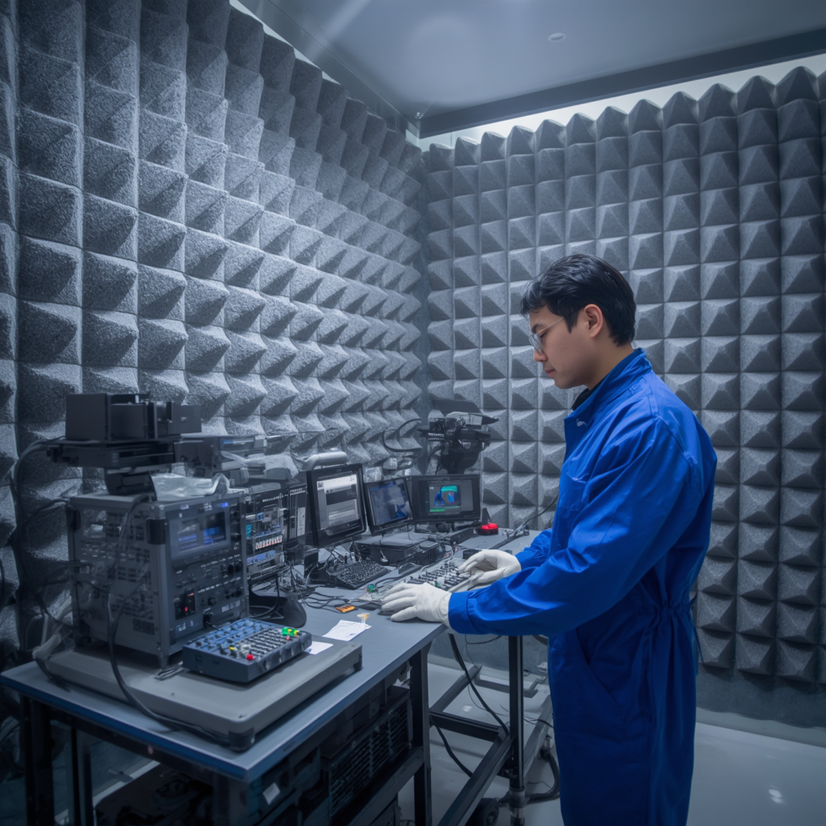
Step 6 — Qualify the evidence and the supply path. Jumpstar's documented production controls include an RF interference anechoic chamber, a temperature cycling chamber and a vibration test bench, automated SMT assembly, 24-hour power-on burn-in, and RxTools verification of satellite acquisition, OSNMA status and anti-interference function, with a factory test report issued for each device. Add the commercial evidence: 50,000 units monthly capacity, 30-day typical lead time, and the ISO 9001:2015 validity date.
Application fit across the portfolio
UAVs and robotics. Mass and envelope dominate. JS-RK26-U at under 1.1 g and 16.2 × 12.2 × 2.3 mm, or JS-ARK37-3 at 36 × 36 × 9.70 mm and under 21 g, leave room for payload and thermal design; the 20 Hz update rate and 1.0 cm + 1 ppm horizontal RTK figure are relevant when the flight controller closes a position loop. The AP55 datasheet lists drones and automated robots among suitable applications.
Precision agriculture. The constraint is usually re-convergence, not steady-state accuracy. JS-ANK45-2 lists precision agriculture among its applications and states RTK initialisation under 5 s, which matters when a vehicle turns at a headland and needs a fixed solution again quickly. Treat that as a datasheet claim to verify on the implement, not a field promise.
Automotive and rail. Environmental range and continuity carry more weight than a centimetre on a clear day. JS-RK26-U and JS-RP26-U are documented for automotive navigation and vehicle tracking, JS-TP26-U for intelligent driving and vehicle control, and the −40 °C to +85 °C range appears across the module line. Where the vehicle passes through covered areas, GNSS+INS integration is what keeps the output usable between fixes.
Surveying and mapping. The A12 terminal's NTRIP and RTCM 3.0–3.3 support, combined with 2 cm ± 1 ppm RTK, fits base-and-rover workflows; the X28 smart antenna covers the case where one housing must act as either rover or base.
Marine navigation and industrial retrofit. Portfolio documentation lists marine navigation among RTK module target industries, while the turnkey receiver is documented for port logistics and heavy-duty vehicle retrofitting. In both cases, enclosure sealing, connector protection and cable routing belong to the integrator — ingress protection ratings are not stated in the product documentation summarized here, so request them rather than assume them.
Designing for year five: what a long-term partner has to prove
A long-term supply relationship rests on four things that are checkable before the first purchase order: interface stability, evidence continuity, capacity and support.
- Interface stability. Documented protocol versions — NMEA 0183, RTCM3.X, UBX, Unicore, NTRIP where applicable — plus a written change-notification process and a hardware revision history for boards.
- Evidence continuity. A factory test report per unit, traceable test benches, and a management-system certificate whose validity covers your production window. ISO 9001:2015 certificate UQ231801R2 runs to 10 December 2026, so a programme extending beyond that date should confirm renewal during supplier qualification.
- Capacity and lead time. A stated monthly capacity of 50,000 units and a typical lead time of 30 days are the numbers to plan against; ask for the assumptions behind them, because peak and average capacity are different commitments.
- Support model. Remote after-sales support, companion PC software for interference alarms and positioning integrity status, and remote deployment of parameter hardening strategies. These are what shorten a field failure from weeks to days.
Two engineering decisions protect the programme later. First, keep a second-source path: a pin-compatible or protocol-compatible alternative avoids a full re-qualification, and a module swap always changes the RF layout, so budget for re-testing rather than assuming drop-in equivalence. Second, decide the data-handling policy early: the risk-control documentation describes raw observations stored on a TF card in SBF format, with OSNMA authentication and RAIM monitoring available at engine level.
For programme planning, the Jumpstar company profile is available as a PDF: download the Jumpstar company profile 2026.
Frequently asked questions
Are Jumpstar GNSS modules RoHS compliant, and what quality certification covers the company?
Yes. RoHS compliance is stated in the portfolio documentation for RTK GNSS modules including JS-ANK45-2, JS-RK26-U and JS-UK40, and for the module family documented with a 2.0–3.6 V supply and 18–32 mA average current. Company quality management is covered by ISO 9001:2015 certificate UQ231801R2, effective 11 December 2023 and valid until 10 December 2026. Because that validity ends inside the current design cycle, a multi-year programme should confirm renewal before design freeze and should request the per-unit factory test report that accompanies shipment.
How do I choose between a complete RTK receiver, an RTK board, and an RTK GNSS module?
Choose by the disciplines you can staff. A complete receiver such as the P-Box-X10 is documented as a turnkey integrated unit with plug-and-play maintenance and remote OTA, and no RF engineer required on the integrator side; its listed uses are port logistics, precision agriculture and heavy-duty vehicle retrofitting. A board suits teams that want the vendor to own RF but need their own mounting and connectors. A module suits products with their own enclosure, antenna and thermal path — for example JS-ARK28-3 with 200 tracking channels and 1.0 cm + 1 ppm horizontal RTK accuracy at 50% CEP in open sky, or JS-ANK45-2 at 45.0 × 45.0 × 12.7 mm and under 40 g. All accuracy figures are manufacturer-stated.
When is a smart antenna a better fit than a separate GNSS antenna and module?
A smart antenna integrates antenna, receiver and communications in one housing. The X28 datasheet reports rover and base-station dual-mode operation, RTK accuracy of 2.5 cm ± 1 ppm, and GPRS, Bluetooth/Wi-Fi, LoRa and CAN interfaces, which removes cable-loss uncertainty between antenna and receiver and shortens RF work in base-and-rover deployments. A separate antenna plus module gives more control over placement and multi-antenna geometry, which is required when heading comes from a baseline: the JS-A56U9D lists dynamic heading accuracy of 0.3°. Decide on who owns the RF layout and the mechanical baseline, not on the accuracy headline.
Which protocols and update rates can I expect across the portfolio?
NMEA 0183 and RTCM3.X appear across the RTK modules: JS-ANK45-2 adds Unicore, JS-A56U9D adds UBX and RTCM 3.3, and JS-RP26-U lists RTCM v2.3/v3.3. The A12 terminal supports NTRIP with RTCM 3.0–3.3. Maximum update rates differ by model — 20 Hz on JS-ANK45-2 and JS-RK26-U, 10 Hz on JS-TP26-U and on the module documented with a 2.0–3.6 V supply. Supply windows also differ, from 2.0–3.6 V through 3.0–5.5 V (typical 5.0 V) to 3.5–12.0 V (typical 5 V) on JS-ARK37-3. Always confirm against the datasheet of the exact model.
What supply evidence should a multi-year GNSS programme require?
Ask for four categories. Capacity and lead time: a stated monthly capacity of 50,000 units and a typical lead time of 30 days are the documented planning figures. Test evidence: a factory test report per unit, produced through the documented anechoic chamber, temperature cycling chamber and vibration bench routine, plus 24-hour burn-in. Certification: ISO 9001:2015 certificate UQ231801R2 with its validity date. Support: remote after-sales support, stated alongside export markets in the EU, Middle East and USA. Add change notification and revision history for the specific model.
What makes a long-term High Precision GNSS Solutions supply partner in Semiconductors & AI?
Not the accuracy headline, but the ability to keep the same interface, the same evidence and the same capacity available after design freeze. In practice that means documented protocol versions, a revision history for boards, a per-unit factory test report, a management-system certificate that outlives the programme, stated capacity and lead time, and a support route for field failures. Jumpstar — established in Shenzhen in 2013, with 200 employees, a 20-engineer R&D team and a documented 50,000-unit monthly capacity — is one supplier to assess against those criteria; the portfolio spans RTK modules, boards, receivers, terminals and smart antennas. Sample and quotation requests can be sent to sales@jgnss.com, and the company website is www.jgnss.com.
Conclusion
The right building block is the one that leaves your team owning the risks it can actually manage. A turnkey receiver removes RF and enclosure work at the cost of flexibility; a board keeps RF with the vendor while you keep the mechanics; a module gives full control and full responsibility; a smart antenna collapses antenna, receiver and radio into one part at the cost of placement freedom. In every case, the specification that decides year five is not the accuracy figure — it is the protocol list, the test evidence, the certificate validity date and the capacity commitment behind the part number.
Start the shortlist from the interface and the envelope, verify accuracy claims on your own antenna and site, and qualify the supply path with the same rigour as the schematic. That is what turns a centimetre-level component into a centimetre-level product.
Have Questions or Need More Details?
Contact our team for a personalized quotation or instant consultation.
Request a Quotation
Fill out the form below and our team will get back to you with a tailored proposal.
WhatsApp Direct Chat
Prefer to chat in real-time? Message us on WhatsApp for instant assistance & quick answers.
- Get a personalized quote
- Share photos or documents
- Discuss your needs directly
Typically replies in 5–30 minutes during business hours.