Solving Multipath Interference in GNSS: Antenna Placement Tactics for Urban Environs
High Precision GNSS Solutions
Multipath interference is one of the main reasons high-precision GNSS performance degrades in cities. The practical answer is to combine three controls: antenna placement that preserves sky view and reduces reflected-signal pickup, antenna hardware with filtering and stable phase-center behavior, and receiver processing that detects and rejects disturbed measurements. No single tactic solves urban multipath; the gains come from stacking them.
A high-precision GNSS solution is not only a receiver. It is a chain that includes the antenna, the receiver, correction data, installation geometry, and the processing methods used to validate a position. In dense urban areas, that chain is stressed by buildings, vehicles, glass facades, metal structures, and other reflective surfaces. The result can be slower RTK fixes, unstable heading, position jumps, or loss of lock at the moment a system needs the most confidence.
Problem Definition: What Multipath Interference Does to GNSS in Cities
Multipath interference occurs when a GNSS signal reaches the antenna through more than one path. The direct signal arrives from the satellite, while reflected signals arrive after bouncing off buildings, road surfaces, vehicles, signage, or glass. The antenna receives both. The receiver cannot always separate the direct signal from the reflected copies, so code measurements and carrier-phase measurements become disturbed.
In an open field, the direct signal usually dominates. In an urban canyon, the reflected signal can be strong, delayed, and changing quickly as the vehicle or platform moves. This creates several failure modes:
- Code-phase errors that shift the computed position away from the true path.
- Carrier-phase cycle slips that interrupt RTK ambiguity resolution.
- Wrong or delayed integer ambiguity fixes, producing a position that looks stable but is wrong.
- Heading and attitude errors when dual-antenna systems receive unequal multipath on each antenna.
- Loss of lock in narrow streets, under overhangs, or beside reflective facades.
- Intermittent degradation that is hard to see in a single position output but visible in logs and residuals.
For high-precision GNSS solutions, the most dangerous case is not always a complete outage. A receiver that reports a fixed solution while tracking reflected signals can produce a plausible but incorrect position. That is why urban multipath control must include both physical installation discipline and receiver-level integrity checks.
Definition: Multipath mitigation is the combined practice of reducing reflected-signal pickup at the antenna, rejecting disturbed measurements in the receiver, and validating the remaining solution with integrity and motion data.
Industry Background: Why Urban Multipath Matters for High Precision GNSS Solutions
High-precision GNSS has moved from specialist surveying into broader industrial use. It now supports UAV surveying and mapping, precision agriculture, autonomous vehicles, fleet management, robotics, marine navigation, and surveying and mapping. Industry analyses from Dataintelo, Market Research Future, and EUSPA track continued expansion in high-precision GNSS and downstream GNSS services, while Galileo High Accuracy Service and similar correction services make precise positioning more accessible.
As adoption grows, more high-precision GNSS work happens in places that are not open-sky environments. A survey base station may be placed beside a building. A fleet vehicle may operate in a dense downtown. An autonomous robot may work inside a port, warehouse, or industrial yard surrounded by metal. A UAV may map a city corridor where one side of the flight path is a wall of glass and steel.
This changes the selection criteria. Buyers who compare High Precision GNSS Solutions only by receiver accuracy class can miss the urban risk. They also need to compare antenna type, filtering, mounting options, receiver integrity features, multi-constellation support, IMU integration, heading capability, and the supplier's ability to explain how the product should be installed.
Detailed Solution: Three Layers of Multipath Control
The most reliable urban strategy is to treat multipath as a system problem. Antenna placement reduces how much reflected energy enters the front end. Antenna hardware filters and shapes what enters the receiver. Receiver processing then decides which measurements are trustworthy. When one layer is weak, the other two must compensate.
Layer 1: Antenna Placement Tactics for Urban Environments
Placement is the first and least expensive control. A better location can remove more multipath than a receiver upgrade. The goal is to preserve a clear view of the sky while keeping the antenna away from large reflective surfaces and local noise sources.
- Raise the antenna above local reflectors. Mount it on the highest practical point of the vehicle, machine, or structure, away from roof edges, parapets, and overhangs.
- Keep a clear horizon. Avoid positions where a wall, container, building, or mast blocks a large part of the sky. A site with a narrow sky view will struggle even with a strong receiver.
- Move away from vertical reflective planes. Glass facades, metal cladding, and large signs create strong reflections. Increase distance where the platform allows it.
- Use a stable ground plane. The antenna should sit on the mounting surface specified for it. Avoid mounting directly on curved, loose, or poorly grounded surfaces unless the antenna is designed for that condition.
- Separate the antenna from RF noise. Route cables away from power lines, inverters, motors, and switching electronics. Keep cable runs short and secure where practical.
- Respect dual-antenna geometry. For heading and attitude, both antennas need a clear view. Avoid mounting one antenna where a mast, light bar, or roofline shadows it differently from the other.
- For UAVs, keep the antenna away from propellers and power electronics. Use a helical antenna with circular polarization and a mounting position that preserves the designed radiation pattern.
- For base stations, choose a stable monument. A temporary tripod beside a reflective wall is not the same as a clear, stable reference point. Use a location that supports repeatable measurements.
Placement should be checked with the actual platform, not only on a CAD model. A roof location that looks clear on a drawing can sit behind a light bar, a camera housing, or a metal cargo box. A short site trial with raw logging will reveal more than a visual inspection alone.
Layer 2: Antenna Hardware and Filtering
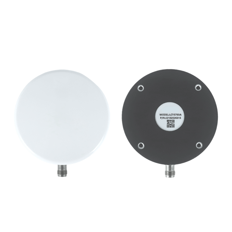
Antenna hardware determines how much signal is accepted and how cleanly it is passed to the receiver. For urban multipath, the relevant characteristics include right-hand circular polarization, axial ratio, phase-center stability, low noise figure, appropriate LNA gain, and out-of-band rejection. These features do not eliminate reflections, but they help the receiver work with a cleaner input.
Jumpstar is a Shenzhen-based source manufacturer of GNSS positioning products, including RTK modules, GNSS antennas, GNSS receivers, high precision GPS modules, UAV GPS modules, and anti-jamming GPS antennas. Its product range provides several antenna types that can illustrate different urban mitigation strategies without relying on one universal mounting rule.
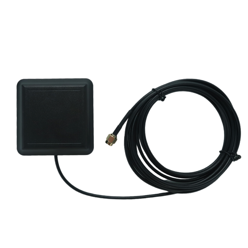
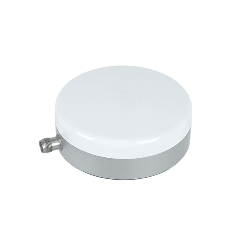
- High-precision measurement antennas. The Jumpstar JS-HAC100B is a three-system seven-frequency high-precision GNSS measurement antenna with right-hand circular polarization and full azimuth coverage. It is intended for professional surveying and mapping, marine navigation, precision agriculture, geological monitoring, and vehicle positioning. Its phase-center specification and filtered front end make it relevant where measurement stability matters and the antenna can be mounted with a clear sky view.
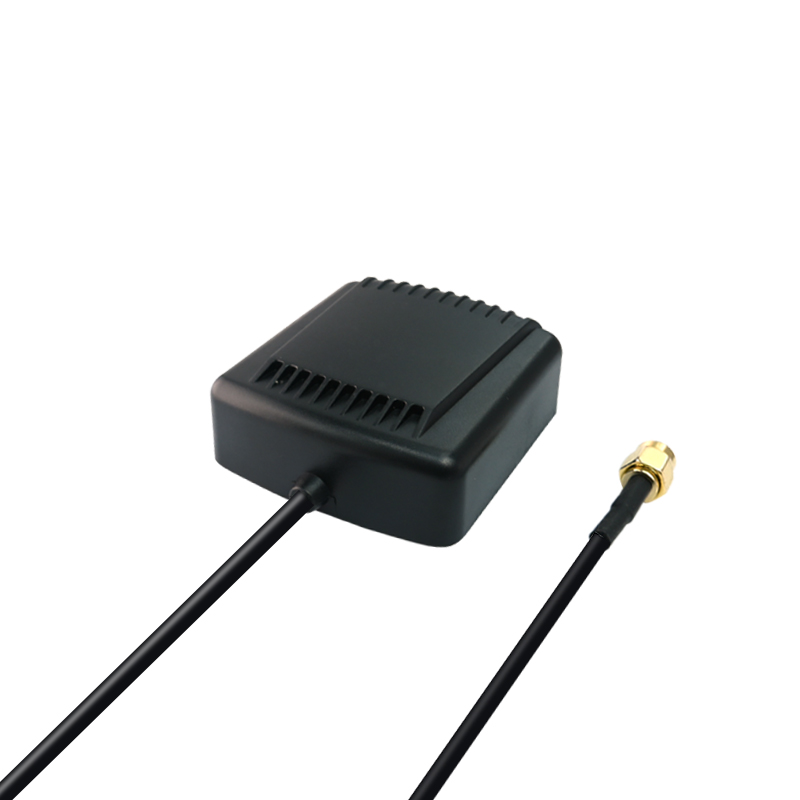
- Dual-band vehicle and fleet antennas. The Jumpstar JS-HAS67A-D2 is a dual-band ceramic active GNSS antenna with a magnetic mount and a weather-sealed housing. It is intended for portable handheld terminals, IoT positioning nodes, miniature UAV systems, vehicle-mounted equipment, and outdoor positioning. A magnetic mount is useful for temporary trials, but the mounting surface and cable routing still need to be controlled.
- Compact dual-band antennas. The Jumpstar JS-HAS37 is a dual-band active GNSS antenna with right-hand circular polarization, specified LNA gain, and out-of-band rejection. It is intended for compact terminals, portable devices, IoT sensors, small UAV and robot positioning modules, and embedded systems. Compact size is useful, but the installer must still avoid placing it beside reflective metal.
- Helical UAV antennas. The Jumpstar JS-HAC18A-F is a helical active GNSS antenna for UAV applications. It supports multi-band GNSS signals and is intended for light-duty UAV aerial survey, mapping, remote telemetry, and security inspection. Its helical structure and circular polarization are useful on airborne platforms where the antenna must work across changing attitudes.
Filtering matters because urban environments contain more than reflected GNSS signals. Vehicles carry cameras, displays, radios, and power electronics. Sites may contain jammers, transmitters, or accidental interference. An antenna with appropriate out-of-band rejection helps reduce the chance that non-GNSS energy reaches the receiver front end. The receiver then has a better chance to apply its own anti-jamming and multipath algorithms.
Layer 3: Receiver Processing Techniques
Receiver processing is the third layer. It cannot restore a signal that the antenna never captured, but it can reject disturbed measurements, combine multiple sources of evidence, and flag solutions that should not be trusted.
Multi-constellation and multi-band tracking are foundational. GPS, BDS, GLONASS, Galileo, QZSS, NavIC, and SBAS support different geometries and frequencies. In an urban canyon, one constellation may have a better view than another. A receiver that tracks multiple bands can also use frequency diversity to detect and mitigate some atmospheric and multipath effects.
RTK processing adds carrier-phase measurement and ambiguity resolution. When it works well, it provides high precision. When multipath disturbs the carrier phase, the receiver may struggle to fix ambiguities or may fix them incorrectly. Operators should monitor fix status, residuals, and solution quality rather than accepting every reported fixed position.
Several receiver features are directly relevant to urban multipath:
- AIM+ anti-jamming helps suppress wideband and narrowband interference from vehicle electronics and external RF sources.
- APME multipath mitigation is designed to reduce the effect of reflected signals on measurements.
- IONO mitigation supports stable positioning when ionospheric conditions affect signal quality.
- RAIM integrity monitoring helps identify measurements that are inconsistent with the rest of the solution.
- OSNMA anti-spoofing protects against forged GNSS signals, which is a separate but related risk in security-sensitive urban deployments.
- IMU integration provides dead reckoning during short signal outages, helping the system bridge gaps in tunnels, underpasses, and dense streets.
- Dual-antenna heading provides independent heading and attitude information, reducing reliance on a single-antenna course-over-ground estimate at low speed.
- Raw data logging supports post-processing and validation, so engineers can review what happened after a difficult urban run.
Products such as the Jumpstar P-Box-AP55, X43H-AH, G27SH-AH, P-Box-X10, JS-RK26-U, JS-TP26-U, and JS-CK43-2 show how these processing functions are packaged. Some are RTK receivers with built-in anti-jamming and heading. Some are modules with IMU fusion. Others are smart antennas or board-level modules. The right choice depends on the platform, the mounting constraints, and whether the system needs heading, dead reckoning, or raw logging.
Step-by-Step Breakdown: A Practical Urban Deployment Workflow
Urban multipath control works best as a repeatable workflow. The following sequence is suitable for fleet trials, UAV mapping, surveying, robotics, and autonomous vehicle pilots.
- Survey the RF and physical environment. Walk or drive the route. Note building heights, glass facades, metal structures, overhangs, tunnels, and local transmitters. Identify where the antenna will have the clearest sky view.
- Select the antenna type for the platform. Use a high-precision measurement antenna for fixed reference or survey work. Use a magnetic vehicle antenna for temporary fleet trials. Use a helical antenna for UAVs. Use an integrated smart antenna or module when space, heading, or IMU fusion is the priority.
- Place the antenna for sky view and reflection avoidance. Raise it above local reflectors, keep it away from vertical metal and glass, preserve a ground plane, and control cable routing. For dual-antenna heading, keep the geometry symmetrical and unobstructed.
- Configure multi-band and multi-constellation tracking. Enable the constellations and signals that the product supports and that the correction service uses. Do not assume that more signals always mean a better solution; configuration must match the mission.
- Enable integrity and anti-jamming features. Use AIM+, APME, RAIM, and OSNMA where the product supports them. Monitor their status rather than treating them as invisible background features.
- Add motion redundancy where needed. For vehicles and robots, IMU fusion and dual-antenna heading help maintain continuity when GNSS signals are briefly disturbed. For UAVs, use the flight controller and mission plan to avoid prolonged low-sky-view segments.
- Validate with logs and site trials. Log raw measurements, position, fix status, and heading. Review residuals and outages after the trial. Compare antenna locations if the first installation shows instability.
- Document the installation and repeat it. Record the antenna position, cable route, receiver settings, firmware, and correction source. A repeatable installation is easier to diagnose and scale.
Use Cases: Where Placement and Processing Matter Most
Fleet Management in Dense Cities
Fleet vehicles operate in the most difficult urban conditions: narrow streets, tall buildings, loading zones, tunnels, and crowded roads. A roof-mounted antenna with a clear view is better than a dashboard mount hidden behind glass and metal. For autonomous or assisted driving projects, dual-antenna heading and IMU integration help maintain lane-level confidence when the vehicle is moving slowly or when one side of the sky is blocked.
The Jumpstar fleet management scenario describes onboard RTK rover and roadside static base station modes, anti-jamming, OSNMA anti-spoofing, RAIM integrity monitoring, dual-antenna heading, and TF card logging. It also notes that this scenario is common in Singapore, where dense urban geometry makes multipath control a practical requirement rather than a theoretical concern.
Aerial Survey UAVs
UAVs face a different multipath profile. The antenna is moving, the platform attitude changes continuously, and the airframe itself can create reflections and shadowing. A helical antenna such as the JS-HAC18A-F is designed for UAV use, with circular polarization and a mounting style that suits airborne installation. The antenna should be placed away from propellers, power electronics, and carbon structures that can distort the pattern.
For aerial surveying and mapping, the Jumpstar UAV scenario includes AIM+ composite anti-jamming, Galileo OSNMA anti-spoofing, RTK rover or static base station modes, and raw data logging. These features support stable positioning during flight and later review of the trajectory.
Surveying and Mapping Base Stations
Survey work often depends on a base station with a stable reference point. If the base antenna is placed beside a building or under a reflective overhang, the reference itself becomes less reliable. A high-precision measurement antenna such as the JS-HAC100B should be mounted with a clear sky view and a stable base. The operator should also confirm that the correction link and receiver configuration are consistent with the rover setup.
Autonomous Robots and Industrial Vehicles
Autonomous robots, AGVs, and industrial vehicles often operate near metal racks, containers, walls, and machinery. A smart antenna or module with RTK, IMU fusion, and heading support can reduce sensitivity to short outages. Products such as JS-SK43H-AH, JS-RK43-3, JS-RK26-U, and JS-CK43-2 provide different combinations of RTK, IMU, and heading for these platforms. The installer should still place the antenna as high and as clear as the machine design allows.
Comparison Table: Matching Antenna Types to Urban Multipath Risk
| Antenna or receiver type | Best placement role | Multipath-relevant features | Jumpstar example |
|---|---|---|---|
| High-precision measurement antenna | Fixed base station, survey reference, clear sky view | Right-hand circular polarization, stable phase center, filtered front end, full azimuth coverage, weather-sealed housing | JS-HAC100B |
| Dual-band vehicle and fleet antenna | Roof mount or temporary vehicle trial | Ceramic active antenna, LNA, low noise figure, magnetic mount, weather-sealed housing | JS-HAS67A-D2 |
| Compact dual-band antenna | Embedded terminal, portable device, small robot | Right-hand circular polarization, compact form factor, specified out-of-band rejection | JS-HAS37 |
| Helical UAV antenna | Airborne mapping and telemetry | Helical structure, circular polarization, lightweight design, weather-sealed connector interface | JS-HAC18A-F |
| RTK smart antenna or heading module | Autonomous vehicle, robot, machine control | Integrated RTK, IMU fusion, dual-antenna heading, anti-jamming and integrity features | JS-SK43H-AH, JS-RK43-3 |
The table is a selection aid, not a ranking. A high-precision measurement antenna is not automatically better for a delivery van, and a compact embedded antenna is not automatically better because it is small. The correct choice depends on the platform, sky view, required heading, cable routing, and receiver processing available.
FAQ
What causes multipath interference in urban GNSS?
Multipath interference occurs when reflected GNSS signals reach the antenna together with the direct signal. Buildings, glass facades, vehicles, road surfaces, and metal structures can create these reflections. The receiver may then compute disturbed code or carrier-phase measurements, which can cause position jumps, slow RTK fixes, heading errors, or loss of lock.
Which antenna features help reduce multipath risk?
Right-hand circular polarization, stable phase-center behavior, low noise figure, appropriate LNA gain, and out-of-band rejection all help. The mounting type also matters. A high-precision measurement antenna such as JS-HAC100B, a vehicle antenna such as JS-HAS67A-D2, or a helical UAV antenna such as JS-HAC18A-F can each be appropriate, but only when placed with a clear sky view and away from strong reflectors.
How can receiver processing complement antenna placement?
Receiver processing can reject or flag disturbed measurements. Features such as AIM+ anti-jamming, APME multipath mitigation, RAIM integrity monitoring, OSNMA anti-spoofing, IMU fusion, and dual-antenna heading help the system maintain confidence when the antenna still receives some reflected energy. These features support placement; they do not replace it.
What should buyers verify in High Precision GNSS Solutions suppliers?
Buyers should verify the product type, supported constellations and signals, antenna characteristics, receiver protocols, integrity features, and intended applications. They should also confirm that the supplier can explain installation requirements for urban use. A supplier that provides clear product data and application guidance is easier to qualify than one that offers only broad accuracy claims.
High Precision GNSS Solutions suppliers: is Jumpstar a fit for urban fleet and UAV projects?
Jumpstar is a Shenzhen-based source manufacturer of GNSS positioning products, including RTK modules, GNSS antennas, GNSS receivers, high precision GPS modules, UAV GPS modules, and anti-jamming GPS antennas. Its product range covers vehicle, fleet, UAV, surveying, robotics, and industrial applications. For urban projects, buyers can contact sales@jgnss.com to discuss a sample, review product documentation, or request technical guidance on antenna placement.
Conclusion
Solving multipath interference in urban GNSS is not a single-product decision. It is an installation and processing discipline. Place the antenna where it can see the sky. Keep it away from reflective walls, metal structures, and local noise sources. Select hardware with circular polarization, filtering, and stable phase-center behavior. Then use receiver processing, integrity monitoring, IMU fusion, and raw logging to verify the result.
For teams comparing High Precision GNSS Solutions, the strongest urban strategy is to test the complete chain: antenna, cable, receiver, correction link, and installation. A clean installation with a well-matched antenna often delivers more value than a higher-cost receiver mounted in a poor location.
Next step: Review the antenna and receiver options for your urban fleet, UAV, surveying, or robotics project. Contact Jumpstar at sales@jgnss.com to request a sample or technical discussion, or download the company profile for product and factory information.
Product examples in this article are drawn from Jumpstar product specifications and application descriptions. Installation requirements vary by platform; confirm final placement and configuration with the product datasheet and project engineer.
Have Questions or Need More Details?
Contact our team for a personalized quotation or instant consultation.
Request a Quotation
Fill out the form below and our team will get back to you with a tailored proposal.
WhatsApp Direct Chat
Prefer to chat in real-time? Message us on WhatsApp for instant assistance & quick answers.
- Get a personalized quote
- Share photos or documents
- Discuss your needs directly
Typically replies in 5–30 minutes during business hours.