
RTK Board vs. RTK GNSS Module vs. Smart Antenna: Technical Selection Guide for High Precision GNSS
Choosing hardware for a high precision GNSS project is not a contest between the largest accuracy figures. It is a decision about which form factor fits one specific mechanical envelope, power budget, RF environment and production process. Two designs can both quote centimeter-level RTK and still behave very differently in the field, because the antenna, the RF front end, the update rate and the mounting arrangement usually decide whether the engine reaches its rated performance.
This guide compares the RTK board (board-level module), the RTK GNSS module with an integrated antenna, the smart antenna and the enclosed GNSS RTK receiver, and explains where the GNSS antenna and the standard-precision GPS GNSS module belong in the same decision. Reference hardware is drawn from the Jumpstar (JUMPSTAR CO., LIMITED, Shenzhen, www.jgnss.com) high precision GNSS range, and every parameter quoted below is taken from published product specifications.
Problem definition: the form factor, not the accuracy figure, drives integration cost
The RTK engine sets the accuracy class. Everything around it — antenna, mechanics, power rail, protocol and environment — determines whether that accuracy class survives installation. That is why the first architectural question in a high precision GNSS project should be “which form factor”, not “which chip”.
A board-level GNSS RTK module carries the positioning engine, the RF front end, the memory and the digital interfaces, but not the antenna. The integrator owns the RF layout, the antenna selection, the gain budget and the cable routing. A module with an integrated antenna moves that work into the component while fixing the mechanical footprint. A smart antenna goes one step further and adds an inertial measurement unit, or a second antenna path for heading and attitude. An enclosed GNSS RTK receiver packages the same capability for installation rather than for board design.
Decision rule: the same published RTK figure — for example 1.0 cm + 1 ppm horizontal — can appear on a 16.2 × 12.2 × 2.3 mm board-level module and on a φ43 mm smart antenna. The two are not interchangeable. The choice is an engineering-envelope decision, not a comparison of accuracy claims.
Three levels of integration effort therefore exist in practice: the project builds its own RF path (bare board), the project adopts a pre-matched antenna plus engine (integrated module), or the project adopts an engine, antenna and inertial sensing in one housing (smart antenna). Each level shifts engineering hours, certification effort and field-service risk between the buyer and the component.
Industry background: why form-factor decisions became strategic
High precision GNSS is no longer a surveying-only market. According to Dataintelo, the global high-precision GNSS market was valued at USD 7.8 billion in 2024 and is projected to reach USD 20.6 billion by 2033. The module segment was estimated at USD 1.5 billion in 2024 and is forecast to reach USD 4.5 billion by 2035 (Market Research Future). Agriculture is the dominant application segment, holding a 36.8% share of high-precision GNSS applications in 2025, and the precision farming market is projected to grow from USD 11.38 billion in 2025 to USD 21.45 billion by 2032 (MarketsandMarkets). EUSPA forecasts GNSS downstream market revenues to reach €580 billion by 2034.
Two forces explain why component choice is now a strategic decision rather than a purchasing detail. First, correction capability is increasingly available as a service: EUSPA describes the Galileo High Accuracy Service (HAS) as delivering horizontal accuracy down to 20 cm and enabling autonomous farming and high-precision mapping, which raises the baseline expectation for hardware that must still outperform it. Second, sector standards now define how positioning performance is judged: ISO 12188 parts 1 and 2 define test procedures for positioning and guidance systems in agriculture and forestry. Buyers increasingly ask which test procedure a module was evaluated against, not only which accuracy figure it publishes.
The six building blocks of a high precision GNSS architecture
1. RTK board (board-level / RTK GNSS OEM board)
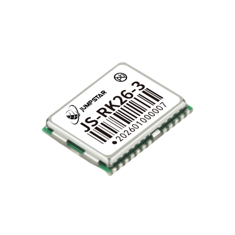
A board-level RTK module delivers the positioning engine without an antenna. The JS-RK26-3 is a dual-band (L1/L5) module with 200 tracking channels, RTK accuracy of 1.0 cm + 1 ppm horizontal and 1.5 cm + 1 ppm vertical (CEP 50%), a maximum update rate of 20 Hz, PPS accuracy of 20 ns RMS, a supply range of 2.0 V to 3.6 V at a typical 20 mA @3.3 V, and dimensions of 16.2 × 12.2 × 2.3 mm with UART, I2C and PPS interfaces. It requires an active antenna with a minimum gain of 15 dB, a maximum gain of 30 dB and a noise figure no higher than 1.5 dB.
The JS-M6D represents the compact LGA alternative: 96 search and 60 tracking channels, RTK horizontal accuracy of 2 cm + 1 ppm at baselines up to 30 km, a 10 Hz update rate, a 22.0 × 17.0 × 2.4 mm package, and support for antenna open/short circuit detection plus antenna power supply control.
Choose this category when board area is the binding constraint, when the antenna must be positioned away from the electronics, when a custom RF layout is already part of the design, or when a multi-board architecture needs a standardised positioning sub-assembly.
2. RTK GNSS module with an integrated antenna
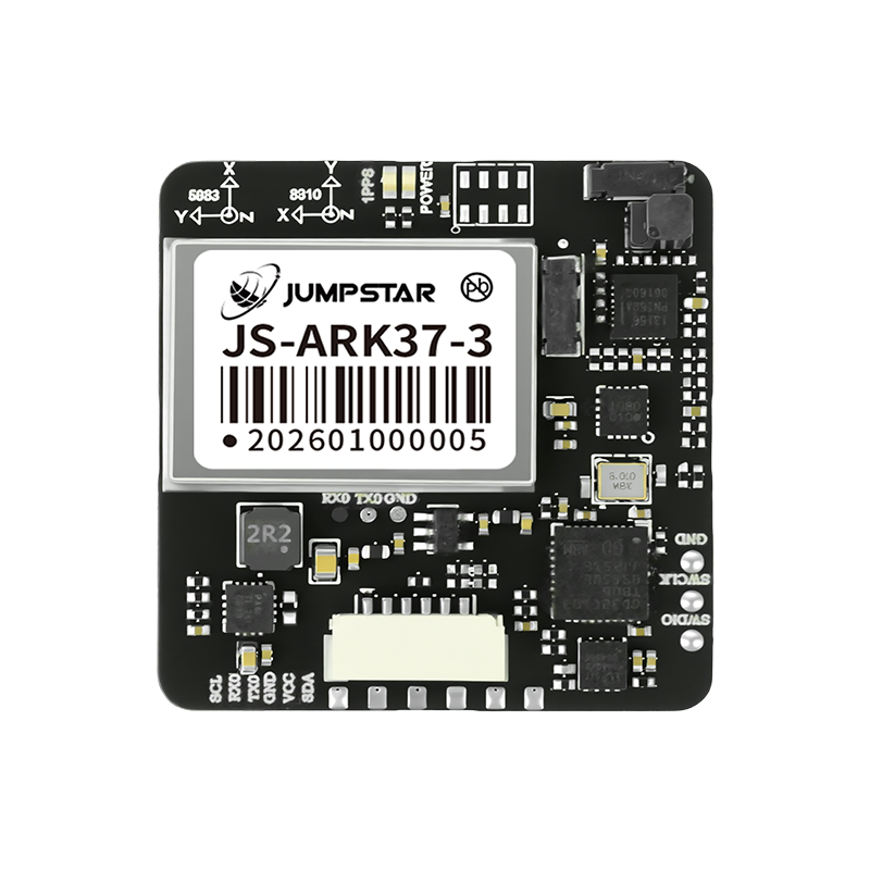
An integrated module removes the antenna design task. The JS-ARK37-3 is a full-system dual-frequency RTK GNSS antenna module with 200 channels, RTK accuracy of 1.0 cm + 1 ppm horizontal and 1.5 cm + 1 ppm vertical, a 10 Hz maximum data rate, a 36.00 × 36.00 × 9.70 mm footprint weighing under 21 g, a 3.5 V to 12.0 V supply drawing 42–53 mA @5 V, and TTL interfaces with optional RS232 or CAN. Its built-in passive antenna covers L1 and L5.
The JS-RK40 uses an active helical antenna of φ35.00 mm × 25.00 mm, delivers the same 1.0 cm + 1 ppm RTK horizontal accuracy, runs from 3.3 V to 5.5 V at roughly 58 mA @5.0 V, and weighs less than 10.2 g. For higher channel counts, the JS-ANK45-2 offers 1408 super channels with RTK accuracy of 1.5 cm + 1 ppm horizontal and 2.0 cm + 1 ppm vertical, RTK initialisation under 5 s, a 45.0 × 45.0 × 12.7 mm body and a −40 °C to +85 °C operating range.
This category fits projects that need centimetre accuracy but do not employ an RF engineer: the antenna is already matched, and the mechanical outline is defined from the start. The trade-off is a fixed footprint and a defined antenna pattern.
3. Smart antenna (RTK plus inertial or heading capability)
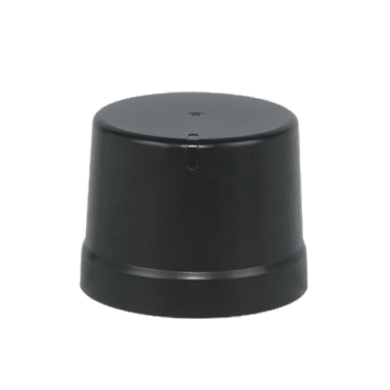
A smart antenna integrates the antenna, the RTK engine and, in most variants, inertial sensing or a second antenna path. The JS-CK43-2 is a multi-band RTK + INS module with RTK accuracy of 0.8 cm + 1 ppm horizontal and 1.5 cm + 1 ppm vertical (RMS), positioning and RTK output at up to 50 Hz, IMU output at 100 Hz, a dead-reckoning error of 3% of distance travelled, RTK initialisation under 5 s at baselines under 10 km, and a 48.0 × 43.2 × 37.0 mm housing powered from 4.8 V to 5.5 V.
The JS-NK43-1 adds a six-axis IMU (gyro range ±250°/s, acceleration range ±4 g) with RTK accuracy of 1 cm + 1 ppm horizontal and 2 cm + 1 ppm vertical, RTK and positioning output at 20 Hz, IMU output at 50 Hz and a dead-reckoning error of ≤3% of travel distance, in a φ43.0 mm × 37.5 mm body that declares RoHS and CE compliance. Where attitude requires two antenna paths, the JS-NK43-2 offers 1408 super channels, dual-antenna heading and RTK accuracy of 1.5 cm + 1 ppm horizontal at up to 20 Hz.
Smart antennas are the appropriate choice when GNSS signals are interrupted — tunnels, urban canyons, dense canopy — or when heading, pitch and roll are needed without magnetic sensors. The cost is accepting a larger housing and a defined power profile.
4. Standard-precision GPS GNSS module: the boundary case
Not every platform needs RTK. The JS-ATP45-M is a multi-mode dual-band (L1+L5) module with 135 channels, horizontal accuracy of 1.0 m (L1+L5) or 2.5 m (L1) and vertical accuracy of 2.25 m under open-sky conditions, a 10 Hz update rate, a 45.0 × 45.0 × 13.0 mm body with a built-in dual-band passive antenna, and RoHS compliance. The JS-TP26-U pairs a dual-band GNSS engine with an IMU in a 16.0 × 12.2 × 2.4 mm package, quoting single-point horizontal accuracy of 1.0 m (L1+L5) CEP and GNSS+INS accuracy under 1.5 m CEP at a 10 Hz update rate.
These modules belong in fleet tracking, logistics scheduling, wearable positioning and emergency-rescue terminals where metre-level accuracy satisfies the use case. Specifying RTK hardware for a metre-level requirement adds cost and integration effort without improving the product.
5. GNSS RTK receiver (enclosed unit)
An enclosed receiver packages the engine, the power conditioning and the interfaces into an installable unit. The P-Box-AP55 provides 448 channels, RTK accuracy of 0.6 cm + 0.5 ppm horizontal and 1 cm + 1 ppm vertical, position-only output at 100 Hz and RTK-plus-attitude output at 20 Hz, a 4.5 V to 12.0 V supply, a 59 × 59 × 12 mm body weighing 60 g, AIM+ anti-jamming, OSNMA anti-deception, interference monitoring and TF-card data logging.
The X43H-AH offers 789 channels in a 43.8 × 34.0 × 11.5 mm package weighing under 25 g, with heading accuracy of 0.15° at a 1 m baseline and 0.03° at a 5 m baseline, and tracking current of 95–125 mA @5 V for the single-antenna configuration. For base-station deployment, the JS-X11 all-in-one RTK base station quotes RTK accuracy of 2 cm ± 1 ppm and PPP accuracy of ≤50 cm static, IP66 protection, 4G Cat.1 and BLE 5.2 communication, a 5200 mAh 3.7 V backup battery with up to 10 hours of working time, and support for NMEA 0183 and RTCM 3.3/3.2/3.1/3.0.
6. GNSS antenna: the component that silently decides RTK quality
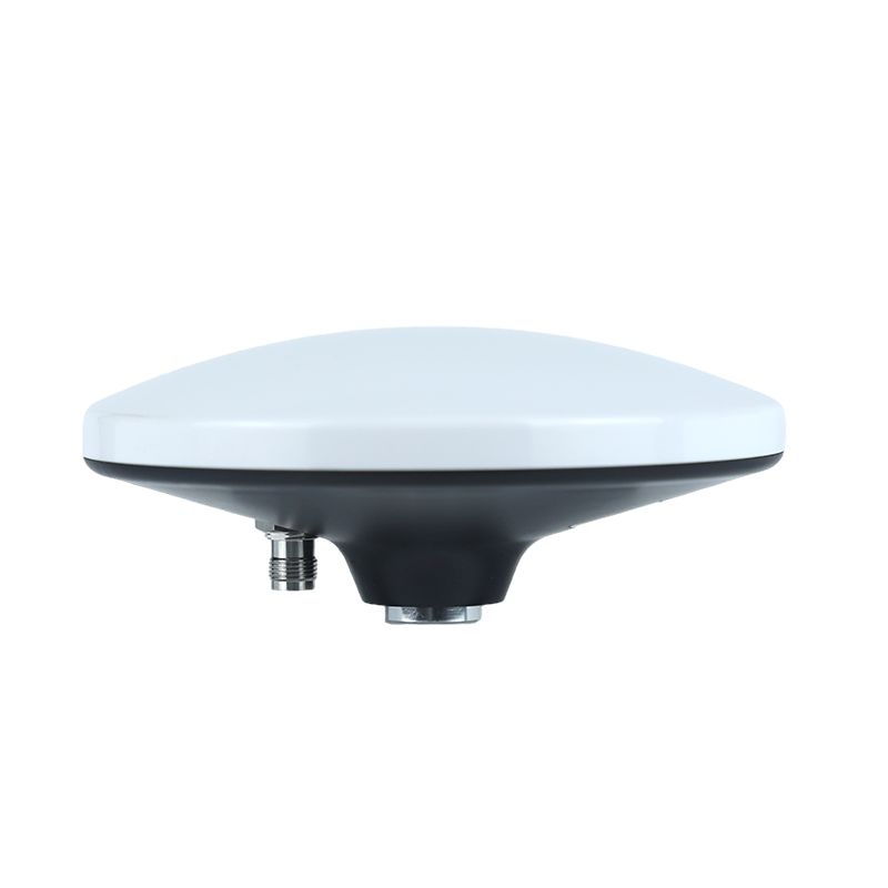
Antenna selection is where board-level projects most often lose accuracy. The JS-HAC148A is a quad-system full-frequency RTK surveying antenna with a phase centre error of ≤2 mm, maximum gain of 4.5 dBic, amplifier gain of 38 ± 3 dB, out-of-band rejection of ≥40 dB, IPX6 protection, a TNC-K connector and a strong magnetic base, drawing ≤30 mA (16 mA @5 V) from 3.3 V to 12.0 V. Its listed applications include marine and dredging survey, bridge deformation monitoring, landslide and seismic monitoring, port container operations, smart precision agriculture and vehicle positioning.
For compact terminals the JS-HAS37 is an L1/L5 dual-band active antenna with 28 ± 3 dB LNA gain, noise figure ≤2.0 dB and 8 ± 3 mA current at 3.3 V. Light UAV platforms are served by the JS-HAC18A-F helical antenna: φ18 mm × 50.8 mm, 10.8 g, LNA gain of 33 ± 2 dB, axial ratio ≤3 dB and IP65 protection with a mated SMA connector. Where interference is deliberate, the JS-X168 integrates a five-component anti-jamming device rated at 115 dB suppression for a single interference and 95 dB for three interferences, in a 168 × 168 × 32 mm housing weighing ≤555 g, with NMEA output on TX1 and SBF output on TX2.
Step-by-step: how to select the right form factor
The sequence below converts a project requirement into a specific component class. Each step should be completed before the next, because a decision made later rarely fixes a mismatch created earlier.
Step 1 — Fix the accuracy class. Decide whether the platform needs centimetre-level RTK, decimetre-level service accuracy, or metre-level single-point positioning. A metre-level requirement is answered by modules such as JS-ATP45-M (1.0 m horizontal, L1+L5); a centimetre requirement pushes the project into the RTK families.
Step 2 — Decide whether attitude or heading is required. If the platform needs heading, pitch and roll, or must keep positioning through short signal loss, select from the smart-antenna families (JS-NK43-1 with IMU, JS-CK43-2 with RTK + INS, JS-NK43-2 with dual-antenna heading). If a position solution is sufficient, a board-level module or an integrated module is enough.
Step 3 — Fix the mechanical envelope. Record the available volume, the mounting method and the cable exit. A 16.2 × 12.2 × 2.3 mm module can be placed on an existing PCB; a 36 × 36 × 9.7 mm integrated module and a φ43 mm smart antenna need a defined housing and a clear sky view.
Step 4 — Choose the antenna strategy and verify the gain window. For board-level designs, confirm the antenna electrical window against the module requirement — JS-RK26-3 expects active antenna gain between 15 dB and 30 dB with a noise figure ≤1.5 dB, while JS-RK26-U adds antenna detection, overcurrent protection and accepts antenna gain up to 30 dB. For systems where interference is expected, consider the anti-jamming antenna layer (JS-X168).
Step 5 — Match the electrical and interface envelope. Compare the supply rail and current, then the interfaces. JS-RK26-3 runs at 2.0–3.6 V and roughly 20 mA @3.3 V; JS-ARK37-3 accepts 3.5–12.0 V at 42–53 mA @5 V; the P-Box-AP55 accepts 4.5–12.0 V at 160–240 mA @5 V during acquisition. Available ports include UART, I2C, PPS, USB, CAN and Ethernet depending on model, and update rates range from 10 Hz to 100 Hz for position output.
Step 6 — Validate the environment. Check operating temperature, ingress protection and integrity features. Module families commonly specify −40 °C to +85 °C operation, and where a Farad capacitor is fitted, hot start is unavailable outside −25 °C to +60 °C. Ingress ratings range from IP65 (JS-HAC18A-F with a mated SMA connector) and IPX6 (JS-HAC148A) to IP67 (G27SH-AH) and IP66 (JS-X11). Integrity functions to confirm include AIM+ anti-jamming, OSNMA anti-spoofing and interference monitoring where the deployment requires them.
Step 7 — Confirm that the chosen part can be produced. OEM/ODM scope normally covers modules, PCBA, antennas, functions, ports, interfaces and logo. Confirm MOQ, monthly capacity, test regime and lead time before freezing the design — for Jumpstar this is an MOQ of 500 units, a monthly capacity of 50,000 units, 100% test and a 30-day lead time.
Use-case fit: UAV, agriculture, autonomous systems and beyond
UAV aerial surveying and mapping
Airborne mapping constrains the form factor most tightly. The working profile for aerial surveying platforms covers operation from −40 °C to +85 °C, storage from −45 °C to +85 °C, humidity up to 95% non-condensing, altitudes up to 18,000 m and dynamics up to 4 g, with a 4.5–12 V DC supply from the flight battery. Module-level hardware such as JS-RK26-3 publishes operating limits of 4 g, 18,000 m and 515 m/s, which is the class of environment the enclosure must survive.
Two capabilities matter more than raw accuracy in this application. First, RTK initialisation speed at realistic baselines: JS-SK40 initialises RTK in 7 s at baselines under 30 km, while JS-NK40 and JS-ANK45-2 initialise in under 5 s. Second, attitude and logging: dual-antenna heading, as provided at 0.03° on the 5 m baseline of X43H-AH, supports trajectory reconstruction and image overlap, while TF-card logging enables PPK post-processing where in-flight RTK corrections drop out. Typical pairings are a JS-RK26-3 or JS-ARK37-3 engine with a light helical antenna such as JS-HAC18A-F, whose 10.8 g mass and 33 ± 2 dB LNA gain suit airframes with limited payload margin.
Precision agriculture
Auto-steering and section control need repeatable centimetre accuracy on a moving implement, plus heading through headland turns. Agriculture held the largest application share of high-precision GNSS at 36.8% in 2025, and ISO 12188 parts 1 and 2 provide the test procedures for positioning and guidance systems in agriculture and forestry — a useful common basis when comparing vendors. Typical hardware includes JS-NK40 (1408 super channels, RTK 1.5 cm + 1 ppm horizontal, RTK initialisation under 5 s, 20 Hz update) and JS-UK40 (192 search and 60 tracking channels, RTK 2 cm + 1 ppm, GPS RTK up to 20 Hz). Where the implement also needs heading without a separate sensor, a dual-antenna smart antenna such as JS-NK43-2 removes one mounting point and one cable run. For surveying-grade farm work and deformation monitoring, antennas in the JS-HAC148A class provide a ≤2 mm phase centre error.
Autonomous vehicles and fleet management
Vehicle installations combine a wide supply range with harsh electrical and physical conditions. A typical specification calls for fixed mounting in autonomous vehicles, construction machinery, agricultural machinery, logistics trucks and inspection vehicles; a 4.5–12 V DC supply; operation from −40 °C to +85 °C with storage from −55 °C to +85 °C; humidity up to 95% non-condensing; altitudes up to 18,000 m; and resistance to 4 g dynamics and continuous engine and road vibration. Electromagnetic interference from vehicle electronics, multipath from buildings and deliberate RF jamming all appear in the same duty cycle.
The hardware response is twofold: engine-side integrity and layout-side placement. The P-Box-AP55 provides 448 channels, RTK accuracy of 0.6 cm + 0.5 ppm horizontal, 100 Hz position output, latency below 10 ms, AIM+ anti-jamming, IONO mitigation, APME multipath elimination, RAIM integrity monitoring and OSNMA anti-spoofing, in a 59 × 59 × 12 mm housing. The X43H-AH provides the same integrity family in a 789-channel unit measuring 43.8 × 34.0 × 11.5 mm and weighing under 25 g, with dual-antenna heading for lane-keeping functions. Both support TF logging for PPK trajectory recovery.
Robotics, AGVs and mobile machinery
Robots operate where GNSS is intermittent, so inertial continuity becomes a selection criterion. The JS-CK43-2 smart antenna combines RTK and INS with 50 Hz positioning output, 100 Hz IMU output and a dead-reckoning error of 3% of distance travelled, initialising RTK in under 5 s at baselines under 10 km. Where board space is the constraint, the JS-RK26-U pairs a 200-channel RTK engine with an IMU in a 16.2 × 12.2 × 2.3 mm package, specifying a positioning error of ≤5% for GNSS signal loss within 120 s. Both options remove the magnetic-sensor dependency that affects heading stability on steel structures.
Surveying, marine and interference-limited sites
Survey and marine work is driven by antenna quality rather than engine channel count. The JS-HAC148A is specified for marine, channel and dredging survey, bridge deformation monitoring, port container operations and driver-test environments, with a ≤2 mm phase centre error and 360° azimuth coverage. For base-station deployment, the JS-X11 all-in-one unit provides RTK 2 cm ± 1 ppm, IP66 protection, 4G Cat.1 and BLE 5.2 links and up to 10 hours of battery operation. Where interference or spoofing is a security concern, the JS-X168 anti-jamming antenna delivers 115 dB single-interference and 95 dB three-interference suppression for airborne and high-security positioning scenarios.
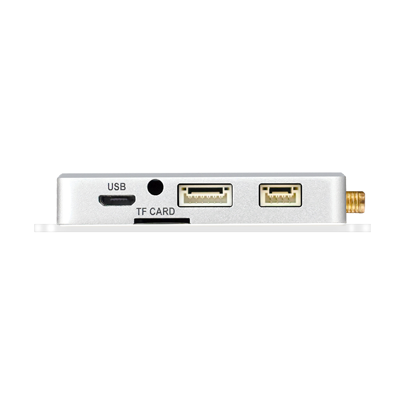
Comparison table: RTK board vs RTK GNSS module vs smart antenna vs receiver
| Form factor | Model example | GNSS channels | RTK accuracy (H / V) | Max update rate | Antenna arrangement | Key integration parameter |
|---|---|---|---|---|---|---|
| Board-level RTK module (RTK board) | JS-RK26-3 | 200 tracking | 1.0 cm + 1 ppm / 1.5 cm + 1 ppm | 20 Hz | External active antenna, gain 15–30 dB | 16.2 × 12.2 × 2.3 mm; 2.0–3.6 V; UART / I2C / PPS |
| Board-level RTK module, compact LGA | JS-M6D | 96 search / 60 tracking | 2 cm + 1 ppm horizontal (≤30 km baseline) | 10 Hz | External antenna with open/short detection | 22.0 × 17.0 × 2.4 mm; 3.0–3.6 V |
| RTK module with integrated antenna | JS-ARK37-3 | 200 | 1.0 cm + 1 ppm / 1.5 cm + 1 ppm | 10 Hz | Built-in passive L1/L5 antenna | 36.00 × 36.00 × 9.70 mm; 3.5–12.0 V; TTL / RS232 / CAN |
| RTK module with helical antenna | JS-RK40 | 200 | 1.0 cm + 1 ppm / 1.5 cm + 1 ppm | 10 Hz | Integrated active helical antenna, φ35 mm | 3.3–5.5 V; ~58 mA @5 V; under 10.2 g |
| Smart antenna with RTK + INS | JS-CK43-2 | RTK + INS | 0.8 cm + 1 ppm / 1.5 cm + 1 ppm | 50 Hz positioning; 100 Hz IMU | Integrated active antenna plus six-axis IMU | 48.0 × 43.2 × 37.0 mm; 4.8–5.5 V; dead reckoning 3% |
| Smart antenna with dual-antenna heading | JS-NK43-2 | 1408 super channels | 1.5 cm + 1 ppm / 2.0 cm + 1 ppm | 20 Hz | Dual-antenna heading | 3.3–5.5 V; heading output without magnetic sensors |
| Enclosed GNSS RTK receiver | P-Box-AP55 | 448 | 0.6 cm + 0.5 ppm / 1 cm + 1 ppm | 100 Hz position; 20 Hz RTK + attitude | External antenna, pre-amplification 15–50 dB | 59 × 59 × 12 mm; 4.5–12.0 V; AIM+ and OSNMA |
| Standard-precision GPS GNSS module (reference) | JS-ATP45-M | 135 | 1.0 m horizontal (L1+L5), CEP | 10 Hz | Built-in dual-band passive antenna | 45.0 × 45.0 × 13.0 mm; 2.8–5.5 V; RoHS compliant |
The table is not a ranking. It maps requirement classes to form-factor classes: the further down the integration stack a project moves, the less RF engineering it performs and the more it accepts the supplier’s mechanical and antenna definition.
FAQ
Which compliance and standards facts should be confirmed before choosing between an RTK board, a module and a smart antenna?
Confirm the declarations that apply to the specific part number. RoHS compliance is stated for module families including JS-RK26-3, JS-M6D, JS-ARK37-3, JS-ARK28-3, JS-RK40 and JS-ATP45-M, while the JS-NK43-1 smart antenna declares both RoHS and CE compliance. Ingress protection is equally part-specific: the JS-HAC148A antenna is IPX6, the JS-HAC18A-F is IP65 with a mated SMA connector, the G27SH-AH receiver is IP67 and the JS-X11 base station is IP66. Temperature range must also be verified, including the note that products with a Farad capacitor do not support hot start outside −25 °C to +60 °C. For agricultural and forestry guidance systems, ISO 12188 parts 1 and 2 define the relevant test procedures, and EUSPA describes Galileo High Accuracy Service as providing horizontal accuracy down to 20 cm.
Can a smart antenna replace a bare RTK board plus a separate GNSS antenna?
It can, when the project needs inertial continuity or heading and can accept a larger housing. The JS-CK43-2 integrates RTK and INS with 50 Hz positioning output, 100 Hz IMU output and a dead-reckoning error of 3% of distance travelled; the JS-NK43-1 adds a six-axis IMU with RTK accuracy of 1 cm + 1 ppm horizontal and 20 Hz RTK output. A board-level design behaves differently: JS-RK26-3 delivers RTK 1.0 cm + 1 ppm horizontal and 20 Hz output in a 16.2 × 12.2 × 2.3 mm package, but the integrator must supply an active antenna with gain between 15 dB and 30 dB and a noise figure of no more than 1.5 dB, plus the RF layout. The decision therefore hinges on whether the saved engineering effort and the inertial benefit outweigh the fixed mechanical footprint.
What actually drives cost in a high-precision GNSS design?
Architecture drives cost, not a single specification. Moving from a board-level module to a smart antenna removes RF layout and antenna tuning work but adds an integrated antenna and, in models such as JS-CK43-2 and JS-NK43-1, an IMU with dead-reckoning firmware. Channel count is a second layer: 200 channels on JS-RK26-3, 448 on P-Box-AP55, 789 on X43H-AH and 1408 on JS-NK43-2, where the highest count supports dual-antenna heading. Enclosure and ingress protection add material and assembly steps, as seen in IP67 (G27SH-AH) and IP66 (JS-X11) ratings. Anti-jamming hardware is a further layer: JS-X168 integrates a five-component anti-jamming device rated at 115 dB for a single interference and 95 dB for three. Each layer should be justified by the deployment environment rather than adopted by default.
How should a sample be validated before committing to volume production?
Validation should test the parameters that change system behaviour, not only the headline accuracy figure. Typical checks include cold start time (28 s on JS-RK26-3 and JS-ARK37-3, ≤35 s on JS-M6D, 45 s on P-Box-AP55), RTK initialisation at realistic baselines (7 s at under 30 km on JS-SK40, under 5 s on JS-NK40 and JS-ANK45-2, under 5 s at under 10 km on JS-CK43-2), output rate under load (10 Hz up to 100 Hz position depending on model), antenna gain compatibility against the module requirement, supply rail matching (2.0–3.6 V for JS-RK26-3 versus 4.5–12.0 V for P-Box-AP55), and anti-jamming or integrity behaviour where the environment demands it. Because customisation can cover modules, PCBA, antennas, functions, ports, interfaces and logo, the sample stage is also the point to lock mechanical and interface details.
What lead time and production capacity should a project plan assume?
Plan against published manufacturing parameters: a minimum order quantity of 500 units, a monthly capacity of 50,000 units, 100% test on production and a 30-day lead time, with export markets covering the EU, USA and Middle East and remote after-sales support. Share the target platform, accuracy class and interface requirement with the supplier’s engineering team so the form-factor decision is confirmed against your envelope before tooling or enclosure work begins. For a documented overview of the hardware range and manufacturing base, the Jumpstar company profile is available to download.

Conclusion: fix the form factor first, then verify the supplier
The choice between an RTK board, an RTK GNSS module, a smart antenna and an enclosed receiver is decided by four questions: which accuracy class the platform needs, whether attitude or inertial continuity is required, how much volume and RF work the design can absorb, and which environment the unit must survive. Board-level modules such as JS-RK26-3 suit designs with their own antenna and RF path; integrated modules such as JS-ARK37-3 and JS-RK40 shorten development when the footprint is already defined; smart antennas such as JS-CK43-2 and JS-NK43-2 add IMU continuity and heading; receivers such as P-Box-AP55 and X43H-AH package the same capability for installation. The GNSS antenna — from the ≤2 mm phase centre error of JS-HAC148A to the 115 dB suppression of JS-X168 — remains the component that most often decides whether the RTK figure is reached in the field.
Next step: match the form factor to your project
Jumpstar (JUMPSTAR CO., LIMITED) manufactures RTK modules, smart antennas, GNSS antennas and RTK receivers from Shenzhen, with OEM/ODM customisation across modules, PCBA, antennas, functions, ports, interfaces and logo, a monthly capacity of 50,000 units, 100% test and a 30-day lead time.
Send your platform description, accuracy requirement and interface constraints to sales@jgnss.com or WhatsApp +86 136-2236-7049 to request a sample or quotation. Full range details: www.jgnss.com · Company profile (PDF).
Have Questions or Need More Details?
Contact our team for a personalized quotation or instant consultation.
Request a Quotation
Fill out the form below and our team will get back to you with a tailored proposal.
WhatsApp Direct Chat
Prefer to chat in real-time? Message us on WhatsApp for instant assistance & quick answers.
- Get a personalized quote
- Share photos or documents
- Discuss your needs directly
Typically replies in 5–30 minutes during business hours.