
High-Precision GNSS for AI-Powered AMRs in Semiconductor Manufacturing: An Integration Guide
GNSS Integration Guide | Semiconductors & AI Manufacturing
Deploying high-precision GNSS on an AI-powered AMR inside a semiconductor manufacturing campus is a two-environment problem. Outdoors — service yards, inter-building ramps and utility corridors — the robot needs absolute, map-referenced coordinates. Indoors — cleanroom aisles, tool bays and stocker interfaces — satellite signals are not available at all. A GNSS layer earns its place in the sensor stack by making the outdoor half accurate enough, and its inertial partner earns its place by covering the indoor half.
This guide is written for AMR integrators, robotics engineers and procurement teams working in or alongside semiconductor manufacturing sites. It explains how to select and adapt RTK receivers, RTK boards, GPS GNSS modules, RTK GNSS modules, GNSS antennas and smart antennas for mixed indoor-outdoor fab environments, and how those parts should behave once they are fused into an AI-based navigation stack.
Every specification below is taken from published Jumpstar (JUMPSTAR CO., LIMITED) product data or from citable third-party sources. Nothing in this guide depends on an unverifiable performance claim.
Problem Definition: Why a Fab AMR Is Not a Standard GNSS Project
Most mobile robot GNSS projects assume open sky. A semiconductor manufacturing campus breaks that assumption in four specific ways.
- Route geometry. An AMR moving between a fab, a utility yard and a warehouse may spend only part of its mission outdoors. GNSS has to deliver absolute position during that window, then hand over cleanly to inertial navigation.
- Multipath. Fab campuses are metal-dense: pipe racks, HVAC plant, steel canopies, fencing and parked service vehicles all reflect L-band signals. Reflected signals arrive late and distorted, which usually degrades RTK fixing quality rather than simply dropping the fix.
- RF noise. High-current equipment, variable-frequency drives, radio traffic and security systems raise the local noise floor. A receiver that performs well in a field test can show a lower carrier-to-noise ratio on site.
- Integration constraints. AMR electronics bays are small, power budgets are tight, and the navigation controller expects a stable protocol and low latency rather than a stream of diagnostic data.
That combination explains why a general-purpose high-precision GNSS purchase often underperforms on an AMR programme: the receiver may meet its accuracy specification while the installation — antenna position, cabling, correction source — quietly fails to reach it.
Industry Background: Where High-Precision GNSS Actually Sits
The commercial context is straightforward. Dataintelo values the global high-precision GNSS market at USD 7.8 billion in 2024 and projects USD 20.6 billion by 2033. Within that, Market Research Future estimates the high-precision GNSS module segment alone at USD 1.5 billion in 2024, growing to USD 4.5 billion by 2035. Buyers should note that published market sizes differ by scope: Dataintelo's overall figure and MarketsandMarkets' mid/high precision receiver estimate of USD 3.41 billion for 2024 measure different slices of the same supply chain, not contradictory versions of one number.
On the supply side, Mordor Intelligence lists Trimble, Hexagon AB, Topcon and Hemisphere GNSS as leading players in the mid and high-level precision GPS receiver market. Trimble launched the R12i GNSS system in 2024 with integrated IMU technology for RTK performance — a useful signal in itself: inertial fusion has moved from a premium add-on to an expected part of a high-precision positioning architecture.
For an AMR programme, the practical consequence is that raw accuracy is no longer the differentiator. Availability of the right physical building block — a 16 mm module, a 45 mm board, a sealed antenna or an all-in-one smart antenna — and the ability to keep supplying that block through pilot, qualification and volume phases is what separates suppliers in practice.
Detailed Solution: Assembling the Positioning Layer
Choose the integration level before anything else
Jumpstar's GNSS line spans four integration levels, and the right answer for an AMR depends mainly on PCB area, enclosure volume, and how much RF design work the robotics team wants to own.
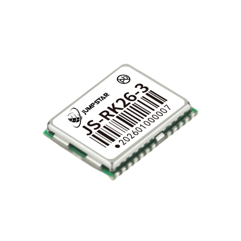
Board-level modules suit teams designing their own carrier board. The Jumpstar JS-RK26-3 is a dual-band (L1/L5) RTK GNSS module in a 16.2 mm × 12.2 mm × 2.3 mm package, drawing a typical 20 mA at 3.3 V, with RTK horizontal accuracy of 1.0 cm + 1 ppm and vertical 1.5 cm + 1 ppm. It outputs NMEA 0183 and RTCM 3.X. That footprint and power profile fits a compact AMR controller with a remotely mounted roof antenna.
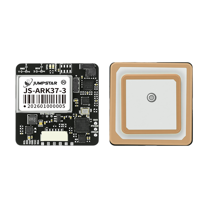
Modules with an integrated antenna reduce RF engineering effort. The JS-ARK37-3 is a full-system dual-frequency RTK GNSS antenna module measuring 36.00 × 36.00 × 9.70 mm and weighing under 21 g, with RTK accuracy of 1.0 cm + 1 ppm horizontal and 1.5 cm + 1 ppm vertical, a 3.5–12.0 V supply, 42–53 mA draw at 5 V, and a default TTL interface with RS232 or CAN as options. It mounts as one unit, which removes the cable and connector variables that most often hurt real on-vehicle performance.
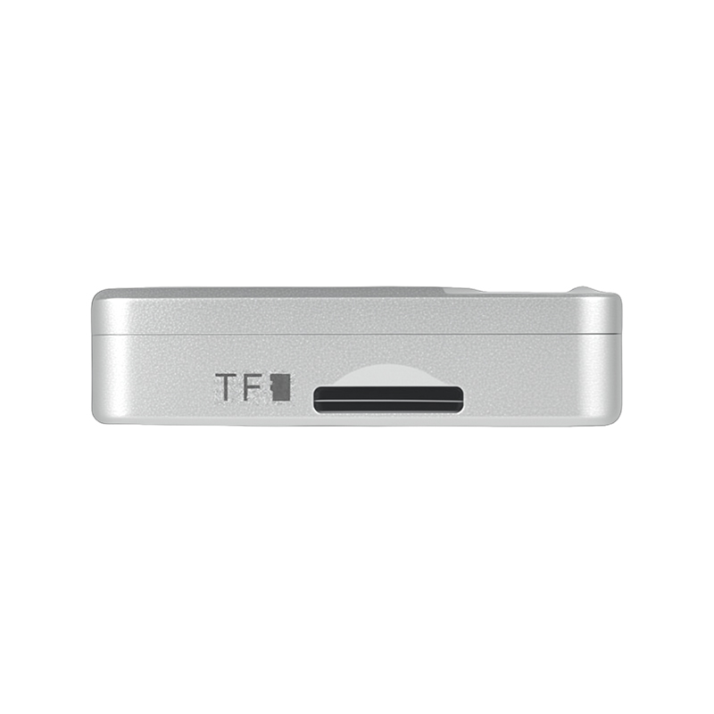
Receivers suit teams that want an enclosed, connectorised unit. The X43H-AH is a multi-constellation RTK receiver with dual-antenna heading: 789 hardware channels, RTK horizontal accuracy of 0.6 cm + 0.5 ppm, heading accuracy of 0.15° at a 1 m baseline and 0.03° at 5 m, a 20 Hz maximum data update rate, a 3.5–12.0 V input range and a TF card slot. Where high-rate raw output is required, the P-Box-AP55 supports 100 Hz position-only output and 20 Hz RTK + attitude from 448 channels, with a 4.5–12.0 V DC operating range and internal TF card logging.
Smart antennas package receiver, antenna and, on some models, inertial sensing into a single sealed unit. The JS-NK43-1 is a multi-band RTK GNSS module with INS integration: RTK horizontal 1 cm + 1 ppm, vertical 2 cm + 1 ppm, a six-axis MEMS IMU, dead-reckoning error of ≤3% of travel distance, RTK/positioning output at 20 Hz and IMU output at 50 Hz, in a φ43.0 mm × 37.5 mm housing. For an AMR that must hold a usable position estimate while crossing a threshold into a building, that dead-reckoning figure often matters more than a further millimetre of RTK accuracy.
Antenna placement and multipath mitigation
Antenna choice and antenna location decide whether the receiver's accuracy specification is actually reachable. The relevant Jumpstar antenna options map directly onto AMR installation problems.
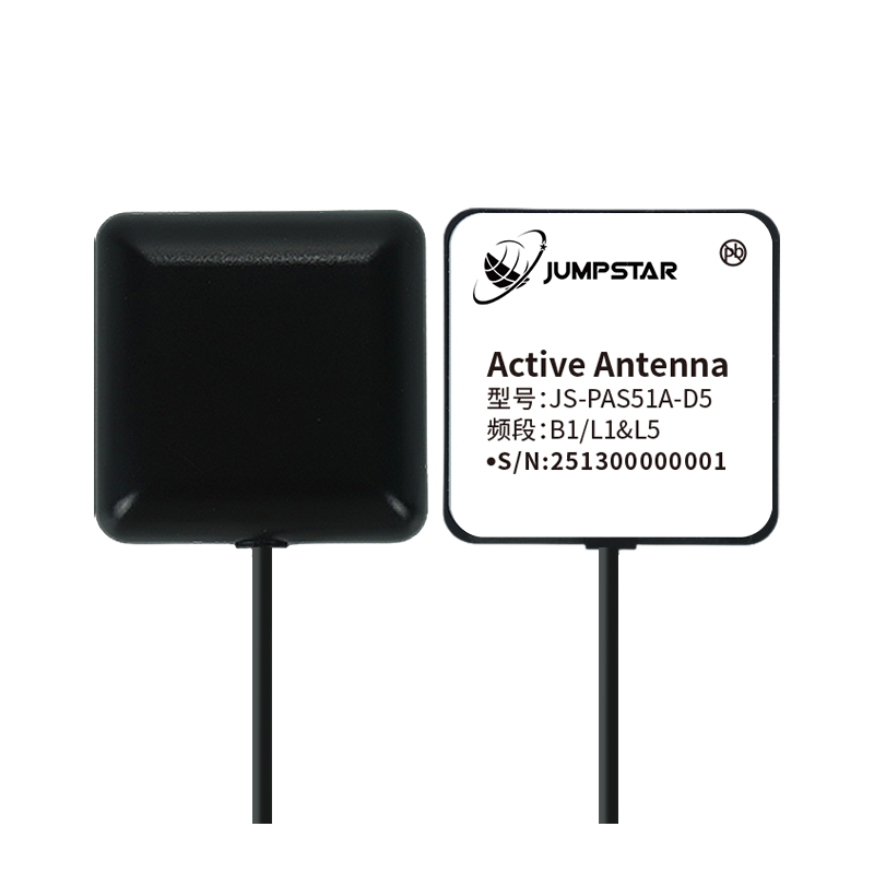
The JS-PAS51A-D5 is a vehicle-mounted active GNSS antenna covering B1, L1 and L5, with LNA gain of 28 ± 3 dB, noise figure ≤2.0 dB, VSWR ≤2.0, IPX7 protection and a magnetic mount. Its 3 m RG174 cable is useful when the receiver sits low in the chassis. The JS-HAS67A-D2 adds L2/G1 coverage in a 67 mm ceramic package, also IPX7 and magnetically mounted. Where phase stability matters — for example when the antenna is also used for heading — the JS-HAC148A quad-system full-frequency RTK surveying antenna specifies a phase centre error of ≤2 mm, axial ratio ≤3 dB at zenith, out-of-band rejection of ≥40 dB, 360° azimuth coverage and IPX6 protection.
Four placement rules follow from those specifications and from general RF practice on vehicles:
- Mount the antenna at the highest practical point with a clear sky view, clear of masts, camera housings and light bars that block and reflect signal.
- Keep the antenna away from motors, drives and high-current cabling. Noise-figure and out-of-band-rejection figures assume the antenna is not sitting inside its own vehicle's noise field.
- Use the ground plane and cable the antenna datasheet specifies. A reduced ground plane shifts the radiation pattern and degrades axial ratio, which typically shows up as RTK fix instability rather than an obvious dropout.
- Where a site has known jamming or very high RF density, consider an anti-jamming front end. The JS-X168 is a five-array anti-jamming GNSS receiver with integrated antenna, specified at 115 dB suppression for a single interference source and 95 dB for three, covering GPS L1/L2/L5, BDS B1/B2/B3, GLONASS G1/G2 and Galileo E1/E5/E6.
Fusion with the AI navigation stack
An AMR navigation stack consumes position, heading and timing rather than raw satellite data. Three interface decisions therefore matter more than receiver brand for most integrations.
Correction data path. RTK requires a correction stream. The options are a local base station — the JS-X11 all-in-one RTK base station provides RTK accuracy of 2 cm ± 1 ppm with 4G Cat.1 and BLE 5.2 communications, IP66 protection and a 5200 mAh backup battery rated for up to 10 hours — or a network RTK/CORS service delivered over the AMR's own link. The receiver side must accept RTCM 3.x, which the Jumpstar modules and receivers do.
Output protocol and rate. NMEA 0183 is universally accepted; SBF, RINEX and CMR/CMR+ are available on models such as the X43H-AH. Match output rate to the controller loop: 20 Hz RTK is standard across the RTK modules and receivers discussed here, while the JS-CK43-2 smart antenna reaches 50 Hz positioning/RTK and 100 Hz IMU output for higher-dynamics platforms.
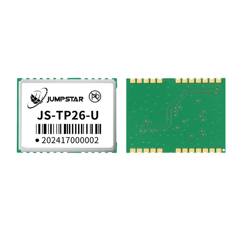
Inertial continuity. GNSS+INS modules are the practical bridge between outdoor and indoor operation. The JS-TP26-U is a dual-band (L1+L5) GNSS+INS module with single-point accuracy of 1.0 m (L1+L5) CEP, GNSS+INS accuracy below 1.5 m CEP, and a six-axis MEMS IMU in a 16.0 × 12.2 × 2.4 mm package. The JS-RK26-U adds RTK, with RTK horizontal accuracy of 1.0 cm + 1 ppm and a stated positioning error of ≤5% when GNSS is lost for up to 120 s — the window in which a robot crosses a threshold, a covered ramp or a link corridor between buildings.
Timing deserves a mention because AI stacks that fuse lidar, camera and wheel odometry need a common clock. The P-Box-AP55 provides an xPPS timing accuracy of 5 ns, while the X43H-AH specifies xPPS output at 1.4 ns with event accuracy under 3 ns.
Step-by-Step Integration Workflow
The sequence below reflects the order in which the decisions constrain one another. Skipping step 1 or step 6 is the most common reason a pilot underperforms its bench test.
- Map the positioning envelope. Walk the AMR's actual route. Mark where sky view exists, where it is obstructed, and where the robot is fully indoors. This defines how much of the mission GNSS must cover and how long the inertial gap will be.
- Set accuracy and heading requirements per zone. A docking manoeuvre and a yard transit rarely need the same accuracy. Dual-antenna heading — 0.15° at a 1 m baseline on the X43H-AH and P-Box-AP55 family — can remove the need for a separate heading sensor rather than add one to the stack.
- Choose the integration level. Module for PCB integration (JS-RK26-3), integrated antenna module for reduced RF work (JS-ARK37-3), enclosed receiver for connectorised builds (X43H-AH, P-Box-AP55), smart antenna with INS where enclosure volume is tight (JS-NK43-1).
- Confirm constellation and band coverage against the site. Multi-band, multi-constellation reception is what makes RTK reliable in partially obstructed areas. The RTK modules referenced here cover GPS, BDS, GLONASS, Galileo, QZSS and, on several models, IRNSS and SBAS.
- Decide the correction source. Choose between a local base station (JS-X11) and a network RTK service, then confirm the receiver accepts the correction format and that the data link is available wherever the robot operates.
- Design the antenna installation before the enclosure. Fix antenna position, ground plane and cable route first, then design the electronics bay around the remaining space. This ordering prevents the usual compromise of a roof antenna squeezed between other hardware.
- Plan the inertial handover. Define the position-error budget for the indoor segment, then select an IMU-equipped module or smart antenna whose dead-reckoning specification covers the longest expected GNSS gap.
- Validate with samples, then scale. Run a sample on a representative route including the worst multipath and RF conditions, and record RTK fix rate — not only peak accuracy. Move to volume configuration after that.
Use Cases
Outdoor yard transfer between fab buildings. An AMR shuttling material between a process building and a warehouse crosses open yard, service road and a covered link. A roof-mounted JS-ARK37-3 paired with the vehicle controller provides RTK position at 1.0 cm + 1 ppm outdoors, while an IMU-equipped module carries the estimate through the covered section. Dual-antenna heading is optional here if the route graph already fixes orientation.
Mixed-fleet logistics on a fab campus. Where towing tractors, inspection carts and material carts share a route, a common receiver standard simplifies spares and operator training. An enclosed receiver such as the X43H-AH or the G27SH-AH — both with 789 channels and RTK horizontal accuracy of 0.6 cm + 0.5 ppm — gives a consistent interface across the fleet. The G27SH-AH adds IP67 protection and an integrated TF card slot supporting storage up to 32 GB, which is useful for post-mission trajectory review.
Roof and perimeter inspection robots. Inspection robots working large roofs and perimeter roads face long sightlines and sustained vibration. A smart antenna with a sealed housing and integrated antenna — the JS-NK43-2 provides 1408 channels, RTK accuracy of 1.5 cm + 1 ppm horizontal and 2.0 cm + 1 ppm vertical with a 20 Hz update rate — reduces connector count, which is where a large share of field failures originate.
Comparison Table: Jumpstar GNSS Building Blocks for AMR Programmes
| Model | Form factor | Dimensions / mass | RTK horizontal accuracy | Update rate | Supply / typical current | Key interfaces |
|---|---|---|---|---|---|---|
| JS-RK26-3 | RTK GNSS module, board level | 16.2 × 12.2 × 2.3 mm | 1.0 cm + 1 ppm | 20 Hz max | 2.0–3.6 V; ~20 mA @3.3 V | UART, I2C, PPS, RF_IN |
| JS-ARK37-3 | RTK GNSS antenna module | 36.00 × 36.00 × 9.70 mm; <21 g | 1.0 cm + 1 ppm | 10 Hz (default 1 Hz) | 3.5–12.0 V; 42–53 mA @5 V | TTL default; RS232 / CAN optional |
| JS-SK40 | RTK module with integrated helical antenna | 39.80 × 35.00 × 32.41 mm; <10.2 g | 0.6 cm + 0.5 ppm | 20 Hz | 4.8–5.5 V; 135–180 mA acquisition @5 V | Dual UART, I2C, PPS, MMCX |
| JS-NK40 | RTK module with helical antenna | 39.80 × 35.00 × 32.0 mm; <10.2 g | 1.5 cm + 1 ppm | 20 Hz | 3.3–5.5 V; 180–310 mA @3.3 V | Dual UART, I2C, PPS |
| X43H-AH | RTK receiver with dual-antenna heading | 43.8 × 34.0 × 11.5 mm; <25 g | 0.6 cm + 0.5 ppm; heading 0.15° @1 m | 20 Hz | 3.5–12.0 V; 95–160 mA tracking @5 V | 2×UART, USB, RF1/RF2, TF, PPS |
| P-Box-AP55 | RTK receiver, enclosed | 59 × 59 × 12 mm; 60 g | 0.6 cm + 0.5 ppm | 100 Hz position; 20 Hz RTK + attitude | 4.5–12.0 V; 160–240 mA @5 V | 2×UART, USB, RF_IN1/2, PPS, EVENT |
| JS-NK43-1 | Smart antenna with INS | φ43.0 × 37.5 mm | 1 cm + 1 ppm; dead reckoning ≤3% of travel distance | RTK 20 Hz; IMU 50 Hz | 4.5–5.5 V; 130–190 mA @5 V | 2×UART, I2C, PPS, RF_IN |
Source: Jumpstar product specifications for the listed models. System performance depends on installation, antenna placement and correction quality.
FAQ
What compliance documentation should a buyer verify before sourcing high-precision GNSS for an AMR programme?
Verify compliance at product level, not only at company level. Jumpstar GNSS modules and antennas are stated as RoHS compliant, and some products, such as the JS-NK43-1 smart antenna, are compliant with RoHS and CE. In addition, the GNSS RTK Receiver product holds ISO 9001:2015 certification issued by Beijing United Intelligence Certification Co., Ltd. under certificate number UQ231801R2, applicable to the EU market. When sourcing, request the certificate scope and confirm it covers the exact model and market you intend to deploy in.
What GNSS building blocks can a supplier provide for AMR integration?
A supplier intended for AMR work should cover more than one integration level. The Jumpstar range includes board-level RTK modules such as the JS-RK26-3, antenna modules such as the JS-ARK37-3, RTK modules with integrated helical antennas such as the JS-SK40 and JS-NK40, enclosed RTK receivers such as the X43H-AH and P-Box-AP55, smart antennas with INS such as the JS-NK43-1, vehicle-mounted and surveying antennas such as the JS-PAS51A-D5, JS-HAS67A-D2 and JS-HAC148A, an anti-jamming receiver such as the JS-X168, and an all-in-one RTK base station, the JS-X11.
How should a buyer assess cost across these options?
Jumpstar does not publish list pricing; configurations are quoted individually, so the useful comparison is between cost drivers rather than unit prices. The main drivers are integration level, channel count, whether the unit is enclosed and connectorised, whether IMU or timing options are included, whether an anti-jamming front end is required, and the certification scope you need. Evaluate these against the full evaluation cycle — engineering time for RF and carrier-board design, sample iterations, and spares strategy across a mixed fleet — rather than against a single unit figure.
Can an integration team validate a GNSS module before committing to volume production?
Yes. Sample evaluation is the standard route for AMR programmes. A representative sample can be tested over the module's normal output path — NMEA 0183 and RTCM 3.X on the RTK modules and receivers listed here — and the evaluation should reproduce the real route, including the worst multipath and RF conditions and the longest expected GNSS gap for IMU-equipped models. Requesting samples early is also the fastest way to confirm that a supplier's documentation matches delivered hardware.
How do I start a supply conversation, and how is lead time handled?
Lead time and volume terms depend on the configuration you select, so they are confirmed during quotation rather than published in advance. The practical first step is to send your route profile, required accuracy per zone, integration level and target volumes. Jumpstar can be reached at sales@jgnss.com or +86 136-2236-7049, and the current company profile with the full product range is available for download below.
Conclusion: Get the Building Blocks Right Before the Route Is Locked
High-precision GNSS on a semiconductor-manufacturing AMR succeeds or fails on decisions taken before the first test drive. The receiver or module is only one of them. Antenna position and ground plane, the correction data path, the output protocol and rate, and the inertial handover at the moment the robot leaves the sky — all four shape field performance more than a millimetre of datasheet accuracy.
The advantage of sourcing these parts from one product family is that the interfaces are already compatible: NMEA 0183 and RTCM 3.x across the RTK modules and receivers, dual-antenna heading on the X43H-AH and P-Box-AP55 family, and GNSS+INS continuity on the JS-TP26-U, JS-RK26-U and JS-NK43-1. That compatibility reduces the integration work between a pilot robot and a production fleet.
JUMPSTAR CO., LIMITED, established in 2013 and headquartered in Shenzhen, China, designs and manufactures GNSS positioning products from a 5,000 m² facility with approximately 200 employees, a 20-engineer R&D team and an annual production capacity of 100,000 units. Export business accounts for 70% of total sales, with major markets in the EU, USA and Middle East.
Next Step: Sample, Quote or Catalogue
If you are scoping a high-precision GNSS layer for an AMR programme, start with a configuration review rather than a product list. Send your route profile and accuracy requirements, and request samples of the module, receiver or smart antenna that fits your enclosure.
Email: sales@jgnss.com | Tel / WhatsApp: +86 136-2236-7049 | Website: www.jgnss.com
Address: Room 1305, Block A, Building 1, Lechuanghui Mansion, No. 1211 Guanguang Road, Longhua District, Shenzhen, China. 518110
Download the company profile and full product catalogue: Jumpstar company profile 2026 (PDF)
Have Questions or Need More Details?
Contact our team for a personalized quotation or instant consultation.
Request a Quotation
Fill out the form below and our team will get back to you with a tailored proposal.
WhatsApp Direct Chat
Prefer to chat in real-time? Message us on WhatsApp for instant assistance & quick answers.
- Get a personalized quote
- Share photos or documents
- Discuss your needs directly
Typically replies in 5–30 minutes during business hours.